Detection of Counterfeit Components
A prime defense contractor offers alternate methods for ferreting out bad parts.
The sale of and resulting use of counterfeit components is a growing problem in the electronics industry.1,2 Detection of these products is crucial for use avoidance and to identify vendors and sources. The most common and obvious means of detection are visual examination and electrical testing. Visual examination answers such questions as: Are the packages the correct size? Is the proper number of leads present, and is symbolization correct? Electrical testing verifies that a component performs to specification. X-ray imaging is also common and reveals features otherwise inaccessible short of destructive analyses.
This discussion points out alternate, less common methods for counterfeit detection. These are important, as often components that seemingly pass incoming inspections may still be counterfeit.3 Examples discussed highlight use of some of these methods and represent examples investigated by the Raytheon Failure Analysis Laboratory, McKinney, TX.
It must be stressed that during an investigation, a finding that suggests a part is counterfeit must be verified beyond the testing itself. For example, if a construction material is identified that is not the same as that on a verified genuine comparison part, the investigators must ensure that this is not accounted for by acceptable changes made by the manufacturer. This underscores that such investigations are often not as straightforward as they may seem.
Vibrational spectroscopies. Fourier Transform Infrared (FTIR) and Raman spectroscopies are very useful at determining material compositions. These methods are sensitive to molecular vibrations, indicating the types of molecular bonding present in samples under investigation. The spectra that result are often likened to “fingerprints” and, as such, can be used for materials verification and identification. These methods are well-known for analysis of suspect counterfeits and fakes, as applied to fields as diverse as pharmaceuticals to the art world.4
Possible uses of these techniques toward counterfeit electronics detection include verification that the correct materials are present on parts, or the detection of foreign materials used to alter parts. In the following example, a verified counterfeit is compared to a genuine part. This demonstrates how these methods helped in detection of the counterfeit.
The package in question had white ink symbolization applied on one side and black ink on the other. The suspect part had correct markings per se; however, it was suspected to be counterfeit. Investigations of the applied inks helped verify this assumption.
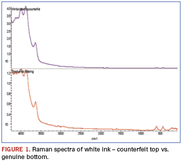
In the Raman spectra (Figure 1), bands beyond 3500cm-1 result from alumina when analyzed using a 532nm laser. The two bands centered around 500cm-1 result from titanium dioxide. Both are used as white pigments. While each is present in the ink on both samples, the ratios are dramatically different.
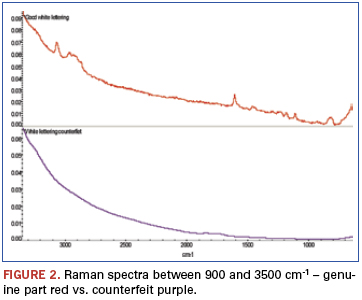
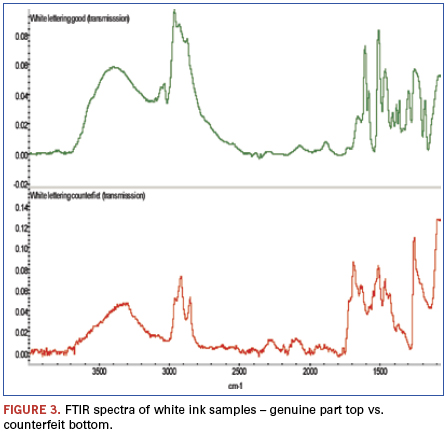
An additional finding (Figure 2) was made from analysis of weak bands between about 900 and 3500cm-1 of these spectra. The bands identified in this region show the genuine part ink to be epoxy-based, while similar bands are missing from the counterfeit part ink spectrum. FTIR was chosen to further investigate these samples (Figure 3). FTIR investigation revealed the base polymers were different: The genuine part was composed of an epoxy-based ink, while the counterfeit was composed of a urethane.
Analysis of the black symbolization using these same methods resulted in similar results: Both inks had the same pigment: carbon black; however, the base polymers were different.
Scanning acoustic microscopy (SAM). Acoustic microscopy is a technique that uses sound waves as opposed to electromagnetic radiation for imaging purposes. It depends on the differences in the speeds which sound waves travel through different media; this is typically a function of material density. As such, it is capable of imaging internal device structure nondestructively via sound waves as they pass through various materials and interfaces between materials. One of the more common applications is detection of voiding within packages. (Sound propagation is much different between gasses and solids.)
In the following example, SAM was used as part of a multi-technique investigation that resulted in verification that a lot of parts was in fact counterfeit; the data were presented to the legitimate part manufacturer, after which verification was confirmed.
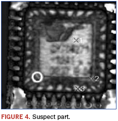
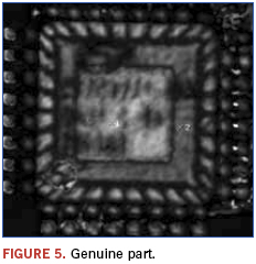
In this example, a lot of programmable grid array devices was suspect. This resulted from visual examination indicating questionable symbolization; poor quality markings and logo differences were noted. Known good devices were on hand and used for comparison purposes. Figures 4 and 5 show the recorded images.
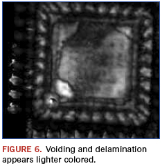
Immediately apparent from the images is that the die and die paddle sizes are different between the suspect and genuine part. Additionally, as shown in Figure 6, the suspect part appears to have possible voiding and delamination as revealed using a technique termed ”C–scan.”
Gas chromatography/mass spectrometry (GC/MS). Gas chromatography is a separatory method that can detect volatile components of a mixture as a function of time that compounds take to travel through the system. This alone is often used for identification of materials; however, this is not typically useful for analyses of unknowns, as residence times are not known. To remedy this problem, GC systems are commonly coupled to MS detectors. This permits determination of molecular identity as a function of the mass of the molecules, and fragments thereof, under investigation. As was the case with FTIR and Raman methods, databases of tens of thousands and even hundreds of thousands of compounds are available for spectral matching and materials identification.
GC/MS is a much nuanced technique, and a multitude of sampling methods are available; these are applied as the samples dictate. The following example will focus on one of the less commonly used techniques, namely “pyrolysis.”5
Pyrolysis refers to the thermal decomposition of large molecules, for example polymers, into smaller fragments by rapid heating under inert atmospheric conditions. This method typically creates a multitude of small volatile molecules readily analyzed using GC methods. The “chromatograms,” sometimes called “programs,” typically contain hundreds or even thousands of peaks. (Each peak represents the detection of a unique compound in the mixture.) These chromatograms can be thought of as fingerprints, often with hundreds of points of reference. As such, this is a very powerful technique to determine if two materials are in fact the same.6 This is important, as many times techniques such as FTIR may indicate that two materials are of the same class, but cannot identify slight compositional differences such as variation in polymer additives between samples. While in the strictest sense MS detection is not necessary, it greatly helps interpreting the often complex data that result.
In the following example, the epoxy encapsulation of a suspect device is compared to a known good device. Suspicions were raised as the devices of a newly received lot had a glossier appearance than an older known good lot (Figure 7). Other analysis techniques could find no differences, and pyrolysis was chosen as the ultimate arbiter.
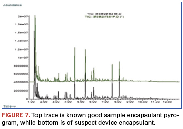
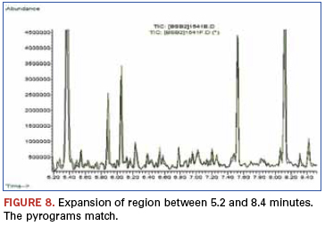
A quick visual examination reveals no noticeable differences between chromatograms. This is further displayed in Figure 8. These data demonstrated that while superficial appearance differences were noted between a suspect part and a known genuine part, the materials used to encapsulate the device were in fact identical. Performance testing also revealed no differences, and the suspect lot was accepted as legitimate.
A metallurgical example. While the following example is not outright counterfeit, it is a case of what is best termed a “misrepresentation” – an example of how counterfeit detection issues are sometimes blurred by shades of gray.
The chemical analysis technique applied in this case was inductively coupled plasma/atomic emission spectroscopy (ICP/AES). This elemental analysis
technique is typically sensitive to low part per billion (ppb) atomic concentrations. It is also very accurate and commonly used for metals and alloy analyses. This example highlights a common problem with metals analyses: Testing results may show the material to be of correct composition; however, the metals still fail via metallurgical defects associated with forging and processing.
In this example, receipt of sub-par balls used on a high-load mission-critical ball bearing is discussed. While this is not an example chosen from a circuit-card assembly perspective (this bearing was not part of a circuit card), parallels exist, as poor quality bearings, in our experience, represent a growing trend and affect mechanical devices that are mounted to printed circuit boards.7
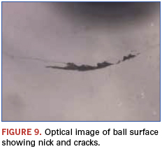
After a bearing had seized during testing, a failure analysis investigation was initiated. As mentioned, compositional analysis using ICP/AES indicated the balls were within specifications. However, visual examination revealed that the balls were of questionable quality; obvious physical defects showed they did not meet the grade standard we believed to be purchasing.
All the cited examples are of balls from bearings that had seen no-to-extremely-limited use and represent forging defects and do not result from wear.
The cracks in this example (Figure 9) radiated out from the nick to cover approximately 33% of the ball diameter. Both defects were well beyond the ball grade thought to have been purchased. These features lead to reliability concerns and the possibility of catastrophic bearing failures.
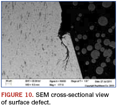
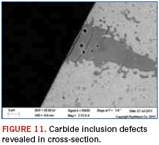
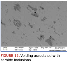
The cross-sectional view in Figure 10 shows that surface defects can radiate into the balls, and the potential for debris creation is heightened. Figures 11 and 12 show that the expected carbide inclusions contained a high degree of voiding and potential initiation sites of further defects when these occur at the surface. In the visually examined samples, about 20% of the balls had these large defects. Eddy current testing was used for screening large numbers of balls, and similar results were found.
While this example highlighted a chemical analysis technique that indicated the materials were within compositional specifications, they were in fact still not as represented. This stresses an important aspect of such analyses: A materials match, or even mismatch, alone is at times not sufficient for counterfeit
verification or even genuine part verification. Often, additional testing and inspection beyond initial investigatory methods are necessary.
The examples cited show a variety of techniques that can be employed during counterfeit detection. The methods cited are certainly not exhaustive, and a number of other techniques such as secondary ion mass spectrometry (SIMS), x-ray photoelectron spectroscopy (XPS), various chromatographic and mass spectroscopic methods, thermal analyses such as thermo gravimetric analysis (TGA) and differential scanning calorimetry (DSC), and a host of others are applicable to these ends.
These examples were chosen to highlight less common approaches to counterfeit detection and to illustrate the, at times, complicated nature of such materials investigations.
References
1. Mike Buetow, “No Counterfeits, No Excuses,” CIRCUITS ASSEMBLY, February 2012.
2. SAE International (Society of Automobile Engineers) has several commentaries at sae.org accessible by searching keyword “counterfeit.”
3. SAE is currently developing standards for use of such methods as part of the G19ATest Laboratories Standards Committee.
4. http://americanpharmaceuticalreview.com/ViewArticleaspx?Content-ID=210andWebExhibits,“Spectroscopy,”webexhibits.org/pigments/intro/spectroscopy.html.
5. Several good reviews are available on the web by simply searching the term GC/MS and variations thereof.
6. Many examples of uses of pyrolysis are available from CDS Analytical; cdsanalytical.com/prod_pyrolisis.html.
7. Karen Field, “Bogus Bearings Look More Real Than the Real Ones,” Electronics Weekly, April 10, 2007.
W. John Wolfgong, Ph.D., is a chemist, James Izzo a senior analyst and Mark Depriest a failure analyst at Raytheon Network Centric Systems (raytheon.com); wolfgong@raytheon.com.


