The DfM Continuum
Setting up the proper feedback loop saves time and cost in re-spins.
When considering electronics product development, design and manufacturing often are thought of as separate processes, with some interdependencies. The processes seldom are considered as a continuum, and rarely as a single process with a feedback loop. But the latter is how development should be considered for the purposes of making competitive, fast-to-market, and lowest cost product.
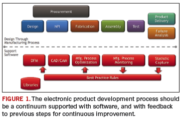
Figure 1 shows the product development process from design through manufacturing to product delivery. This often is a segmented process, with data exchange and technical barriers between the various steps. These barriers are being eliminated and the process made more productive by software that provides for better consideration of manufacturing in the design step, more complete and consistent transfer of data from design to manufacturing, manufacturing floor optimization, and the ability to capture failure causes and correct the line to achieve maximum yields. The goal is to relay the failure causes as improved, best-practice DfM rules and prevent failures from happening.

The process starts with a change in thinking about when to consider manufacturing. Design for manufacturability should start at the beginning of the design (schematic entry) and continue through the entire design process. The first step is to have a library of proven parts, both schematic symbols and component geometries. This forms the base for quality schematic and physical design.
Then, during schematic entry, DfM requires communication between the designer and the rest of the supply chain, including procurement, assembly, and test through a bill of materials (BoM). Supply chain members can determine if the parts can be procured in the volumes necessary and at target costs. Can the parts be automatically assembled or would additional costs and time be required for manual operations? Can these parts be tested using the manufacturer’s test equipment? After these reviews, feedback to the designer can prevent either a redesign or additional product cost in manufacturing.
The next DfM is to ensure the layout can be fabricated, assembled and tested. Board fabricators do not just accept designer data and go straight to manufacturing. Instead, fabricators always run their “golden” software and fabrication rules against the data to ensure they will produce boards that are not hard failures, and to determine adjustments to avoid soft failures that could decrease production yields.
So, for the PCB designer, part of the DfM is to use this same set of golden software and rules often throughout the design process. This practice not only could prevent design data from being returned from the fabricator or assembler, but, if used throughout the process, could ensure that design progress is always forward, with no redesign necessary.
A second element in this DfM process is the use of a golden parts library to facilitate the software checks. This library contains information typically not found in a company’s central component libraries, but rather additional information specifically targeted at improving a PCB’s manufacturability. (More on this later.)
When manufacturing is considered during the design process, progress already has been made toward accelerating new product introduction and optimizing line processes. Design for fabrication, assembly and test, when considered throughout the design function, helps prevent the manufacturer from having to drastically change the design data or send it back to the designer for re-spin. Next, a smooth transition from design to manufacturing is needed.
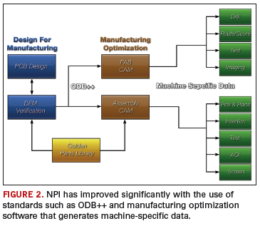
As seen in Figure 2, ODB++ is an industry standard for transferring data from design to manufacturing. This standard, coupled with specialized software in the manufacturing environment, serves to replace the need for every PCB design system to directly produce data in the formats of the target manufacturing machines.

Time was, design systems had to deliver Gerber, machine-specific data for drill, pick-and-place, test, etc. Through standard data formats such ODB++ (and other standards such as GenCAM), and available fab and assembly optimization software, the manufacturing engineers’ expertise can be capitalized on. One area is bare board fabrication. If the designer has run the same set of golden rules against the design, there is a good chance no changes would be required, except ones that might increase yields. This might involve the manufacturer spreading traces, or adjusting stencils or pad sizes. But the risk here is the manufacturer does not understand tight tolerance rules and affects product performance. For example, with the emerging SERDES interconnect routing that supports data speeds up to 10 Gbs, matching trace lengths can be down to 0.001˝ tolerance. Spreading traces might violate these tolerances. It is important the OEM communicate these restrictions to the manufacturer.
From an assembly point of view, the manufacturer will compare received data (pad data and BoM) to a golden component library. Production engineers rely on this golden library to help identity BoM errors and footprint, or land pattern mismatches prior to first run. For example, the actual component geometries taken from manufacturer part numbers in the BoM are compared to the CAD footprints to validate correct pin-to-pad placement. Pin-to-pad errors could be due to a component selection error in the customer BoM. Although subtle pin-to-pad errors may not prevent parts from soldering, they could lead to long-term reliability problems.
Designers have DfT software that runs within the design environment and can place test points to accommodate target testers and fixture rules. Final test of the assembled board often creates a more complex challenge and usually requires a manufacturing test engineer to define and implement the test strategy. Methods such as in-circuit or flying probe testing require knowledge of test probes, an accurate physical model of the assembly (to avoid probe/component collisions), and the required test patterns for the devices.
Manufacturing Process Optimization
Even as a new assembly line is configured in preparation for future cost-efficient production, for high-mix, high-volume or both, simulation software can aid in this process. Many manufacturers are utilizing this software to simulate various line configurations combined with different product volumes and/or product mixes. The result is an accurate “what if?” simulation that allows process engineers to try various machine types, feeder capacities and line configurations to find the best machine mix and layout. Using line configuration tools, line balancers, and cycle time-simulators, a variety of machine platforms can be reviewed. Once the line is set up, this same software maintains an internal model of each line for future design-specific or process-specific assembly operations.
This has immediate benefits. When the product design data are received, creating optimized machine-ready programs for any of the line configurations in the factory, including mixed platforms, can be streamlined. A key to making this possible lies in receiving accurate component shape geometries, which have been checked and imported from the golden parts library. Using these accurate shapes, in concert with a fine-tuned rule set for each machine, the software auto-generates the complete machine-ready library of parts data offline, for all machines in the line capable of placing the part. This permits optimal line balancing, since any missing part data on this or that machine – which can severely limit an attempt to balance – are eliminated. The process makes it possible to run new products quickly because missing machine library data are no longer an issue. Auto-generating part data capability also makes it possible to quickly move a product from one line to another, offering production flexibility.
Programming the automated optical inspection equipment can be time-consuming. If the complete product data model – including all fiducials, component rotations, component shape, pin centroids, body centroids, part numbers (including internal, customer and manufacturer part numbers), pin one locations, and polarity status – is prepared by assembly engineering, the product data model is sufficiently neutralized so that each different AOI platform can be programmed from a single standardized output file. This creates efficiency since a single centralized product data model is available to support assembly, inspection and test.
Managing the assembly line. Setting up and monitoring the running assembly line is a complex process, but can be greatly improved with the right software support. Below is a list of just a few elements to this complex process:
- Registering and labeling materials to capture data such as reel quantity, PN, date code and MSD status.
- Streamlining material preparation and kitting area per schedule requirements, plus real-time shop floor demand, including dropped parts, scrap and MSD constraints.
- Feeder trolley setup (correct materials on trolleys).
- Assembly machine feeder setup, verification and splicing.
- Manual assembly, and correct parts on workstations.
- Station monitoring, capture runtime statistics, efficiency, feeder and placement errors and OEE calculations.
- Call for materials to avoid downtimes.
- Tracking and controlling production work orders to ensure visibility throughout the process.
- Enforcing the correct process sequence is followed, and any test or inspection failure is corrected to “passed” status before product proceeds.
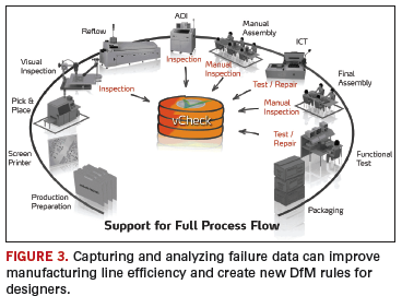
Collecting failure data. It is inevitable some parts will fail. By capturing and analyzing these data, causes can be determined and corrected. Figure 3 shows certain areas where failures are diagnosed and collected using software. One benefit of software is the ability to relate, in real-time, test or inspection failures with the specific machine and process parameters used in assembly and the specific material vendors and lot codes used in the exact failure locations on the PCB.

Earlier, a set of DfM rules in the PCB design environment that reflects the hard and soft constraints to be followed by the designer was discussed. If these rules were followed, we could ensure that once design data reached manufacturing, they would be correct and not require a redesign. What we did not anticipate was that producing a product at the lowest cost and with the most efficiency is a learning process. We can learn by actually manufacturing this or similar designs, and determine what additional practices might be applied to DfM to incrementally improve the processes.
This is where the first feedback loop might help. If we capture data during the manufacturing process and during product failure analysis, this information can be used to improve DfM rule effectiveness. Continuous improvement of the DfM rule set based on actual results can positively influence future designs or even current product yields.
The second opportunity for feedback is in the manufacturing process. As failures are captured and analyzed (Figure 3), immediate feedback and change suggestions can be sent to the processing line or original process data models. Highly automated software support can reconfigure the line to adjust to the changes. For example, software can identity which unique machine feeder is causing dropped parts during placement. In addition, an increase in placement offsets detected by AOI can be immediately correlated to the machine that placed the part, or the stencil that applied the paste, to determine which tool or machine is in need of calibration or replacement. Without software, it would be impossible to detect and correlate this type of data early enough to prevent yield loss, rework or scrapped material.
Design through manufacturing should be treated as a continuum. One starts with the manufacturer’s DfM rules, followed and checked by the designer’s software, the complete transfer of data to the manufacturer using industry-recognized standards, the automated setup and optimization of the production line, the real-time monitoring and visibility of equipment, process and material performance, and finally the capture, analysis and correlation of all failure data. But the process does not end with product delivery, or even after the sale support. The idea of continuum is that there is no end. By capturing information from the shop floor, we can feed that to previous steps (including design) to cut unnecessary costs and produce more competitive products.
John Isaac is director of market development at Mentor Graphics (mentor.com); john_isaac@mentor.com. Bruce Isbell is senior strategic marketing manager, Valor Computerized Systems (valor.com).
Ed.: At press time, Mentor Graphics had just completed its acquisition of Valor.


