Faked Parts Detection
New Techniques to ID Counterfeit ICs
Acoustic micro imaging can reveal whether the die and lead frame are genuine.
SMT Corp. is an independent component distributor. To prevent counterfeit plastic-encapsulated ICs from reaching its customers, it uses multiple detection technologies, including visual inspection, light microscopy, digital stereo microscopy, resistance to solvents testing (RTS), scanning acoustic micro imaging, real-time x-ray, acid etch and mechanical decapsulation for die verification, solderability testing, BGA coplanarity inspection, scanning electron microscopy (SEM), energy dispersive spectroscopy (EDX), and x-ray fluorescence (XRF) inspection. Components identified by SMT as suspect-counterfeit are either turned over to federal law enforcement, government agencies, the IP holder, or ground up onsite and environmentally disposed.
A practical necessity in any method of counterfeit identification is the availability of known genuine components of the same type. Except in instances of truly outlandish components (misspellings on the label, no die in the package, etc.), having genuine parts for comparative analysis makes counterfeit identification much easier, especially in components where some features fall in a gray area. (Are those delaminations extensive enough to prove counterfeiting, or are they just unusually sloppy work by the OEM?)
Component users encounter two different types of counterfeit parts. By far the most common is the “recycled” ICs that began life, generally five to 15 years ago, as a new, genuine component from a legitimate component manufacturer. Eventually the circuit board it resided on was scrapped and shipped offshore, where the entire component population was burned off for refurbishment, remarking, repackaging and reintroduction as new into the global supply chain. SMT Corp. estimates recycled ICs comprise 80 to 90% of all counterfeits currently in circulation worldwide.
A small percentage of counterfeit components are “made-from-scratch” – or knock-offs. A foreign counterfeiter with component manufacturing capability finds it worthwhile to replicate the entire component altogether – and does so without the permission of the original IP holder. The chip and other internal features may be nonfunctional or even absent, or – worse yet – functional!
The vast majority of recycled counterfeits undergo a process something like this: The board is heated in an uncontrolled harsh environment (usually an open-flame fire) until solder reflows, at which time the board is smacked against a hard surface to remove the components. The components from hundreds or even thousands of similar boards are collected and washed (sometimes in a nearby river, sometimes outside in the rain) to remove residue from the high-heat removal process, and then sun-dried. Most are then rough-sorted by sifting and then hand-sorted by part number or similar package style. In many cases, components of different manufacturers, vastly different functions and electrical characteristics wind up in the same finished counterfeit lot, as long as they have the same number of leads and the same package dimensions.
The original component part markings are then removed (generally by rubbing the component by hand against sandpaper tacked to a table). A “blacktop” coating that more or less approximates the texture and color of the original mold compound surface is painted or sprayed onto the component’s top surface to cover the sanding marks. Last, the top surface is reprinted (remarked) with a legitimate-looking manufacturer’s logo, part number and more recent lot/date code. They are then packaged in what looks like (and may actually be) authentic original component manufacturer (OCM) packaging and offered for sale as new product direct from the manufacturer.
The longevity of functioning counterfeits is, of course, questionable indeed. It should be pointed out, given the huge volume of containers recycled each year, that it is perfectly possible for the same component to be recycled multiple times. For the successful counterfeiter, external appearance of authenticity at the point of sale is what matters most; downstream functional issues become someone else’s problem.
The efforts of counterfeiters to mimic the appearance of genuine components involve considerable innovation. While some methods are still crude, many are not.
In July 2009, SMT Corp. was the first to identify a new, harder to detect blacktopping material that, when applied carefully, looked almost identical to the OCM’s top coating. Traditionally the paint-like blacktopping material has easily been identified by a solvent swab of pure acetone, or even a much milder 75/25% mixture of mineral spirits and alcohol. These solvents would dissolve the traditional blacktop coatings and reveal visual evidence left behind by the counterfeit process of removing original part markings.
This new advanced blacktop material is harder to distinguish visually from the surface of a genuine part, and is not affected whatsoever by traditional RTS test methods. An engineer applying traditional solvent testing would conclude it to be a genuine part. SMT believes this advanced blacktop material is made from the dust ground off components and then mixed with a heat-activated epoxy compound before being sprayed on and heat-cured for hardness and durability. In September 2009, Honeywell Aerospace shared its process using a heated solvent called “Uresolve” (made by Dynaloy) that proved effective in removing the new blacktop coating from counterfeit components. The only major drawback to the process was it also could remove the topcoat that OCMs put on the majority of authentic components. (Factory-applied topcoats, like the blacktopping that counterfeiters use, can be scraped off with a razor, but they hide no
sanding marks.)
In January, SMT Corp. further refined that process using a different Dynaloy product called DynaSolve 750. After considerable experimentation on a wide range of counterfeit and authentic parts, a temperature/duration process was identified that completely removed the new blacktop (exposing the sanding marks below) – yet had no effect on the factory-applied topcoats of all authentic components tested. The refined process required the DynaSolve be preheated to 105°C and the suspect component to be half-immersed for 45 min. (Figure 1).
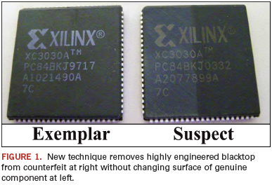
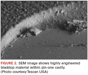
These same components showed other signs of counterfeiting as well. For example, the highly engineered blacktop material had been sprayed onto the top surface, and some had visibly coated the upper portion of the side of the component. In addition, the blacktop material had in some cases been sprayed into the pin-one cavities, with the result that the cavities in close optical view appeared roughly textured rather than perfectly flat and smooth. Figure 2 is a SEM image of a portion of one pin-one cavity that has been partly sprayed. Some cavities, however, were completely clean and resembled those found in genuine parts.
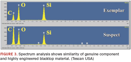
EDX analysis compared the results of the new blacktop material with analysis of the top surface of known genuine components. The results
(Figure 3), while not identical, suggest it is possible that the sprayed-on blacktop had its origins in the dust created by sanding genuine components.
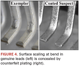
Another clue was found in the leads of the components. At left in Figure 4 is a light microscope view of two leads from a genuine component. Because these leads were straight when coated, the forming process produced some cracking or scaling of the coating at the bend. This is an expected feature on genuine components. But counterfeiters apply coatings to leads that are already bent, so cracking and scaling are absent. The coating applied by counterfeiters also rounds off the lead ends and conceals the copper base metal visible in the cut-off lead ends on the genuine parts.
Most acoustic methods developed by Sonoscan use VHF or UHF ultrasound reflected from material interfaces at a depth of interest such as the die surface, the lead frame of die paddle surface, or the die attach depth. For example, when imaged acoustically, both genuine and counterfeit components treated with DynaSolve at 105°C show some internal delaminations at the lead finger depth not present beforehand, an indication that the test should be
considered destructive.
The same C-SAM acoustic micro imaging system that images internal features can also image surfaces acoustically. It can also characterize a material at the same time it is making an acoustic image.
One of the oldest methods for spotting possibly counterfeit components is the simple application of a single pulse of ultrasound to determine the mold compound’s acoustic impedance (acoustic velocity times density, the product expressed in megarayls). If known genuine parts have an acoustic impedance of around 4.3 megarayls, and an incoming part has an acoustic impedance of 7.6 megarayls, the new part may be a counterfeit, or the legitimate supplier may be using a new mold compound. One recent development: Some made-from-scratch counterfeiters are selecting mold compounds that attempt to match the acoustic impedance of the genuine component.
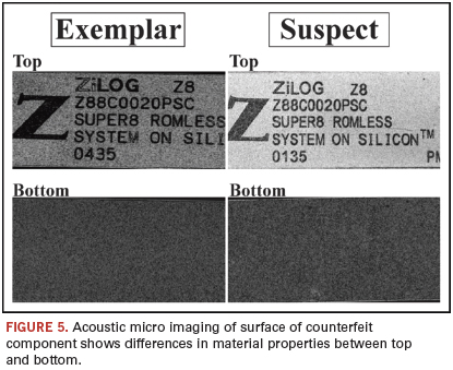
During acoustic imaging of components, it is customary to scan the top surface of the part by itself for reference. The surface image gives no information about features at depth, but it turns out to have value in identifying counterfeits when the bottom surface, which is ordinarily not of interest, is also imaged. In genuine components, both surfaces appear identical acoustically because they were formed from the same material during the same injection molding process. But in a recycled fake where the top has been blacktopped, the two sides often look very different. (Figure 5).
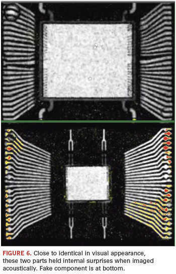
When an acoustic micro imaging system targets a specific depth within a counterfeit, strange things are sometimes found. Figure 6 shows two outwardly identical components having the body dimensions, the same label and the same number of leads. But the acoustic image shows that the component at bottom is either a newer die revision from the manufacturer utilizing a smaller die or is from a different component manufacturer altogether and uses entirely different die and lead frame. It also has small delaminations (red and yellow) on nearly all of the lead fingers.
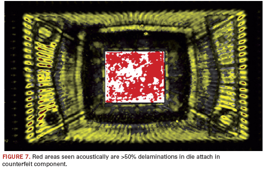
One of the areas of interest in any acoustic image of a component is the percentage of delaminations or similar defects in the die attach material. For example, J-STD-020D, sec. 6.2.1.1, specifies that metal lead frame components may have “no delamination/cracking >50% of the die attach area in thermally enhanced packages or devices that require electrical contact to the backside of the die.” New, genuine components may have some percentage of delamination and be perfectly acceptable for most applications. Recycled components may show a relatively greater degree of delamination, presumably because of the thermal and mechanical stresses of prior use and of the counterfeiting process itself. Figure 7 shows the acoustic image of a known counterfeit component whose die attach delaminations (red areas) exceed the standard. Digital image analysis showed delaminations covered 57.12% of the die attach area.
It may be difficult to tell whether a particular component with above average die attach voiding is simply an isolated item from a good OEM, or whether this component has been heated irregularly, smacked on the ground and washed in a river. Determining whether a part is counterfeit is easier if multiple questionable parts and multiple known genuine parts are available in order to look for patterns. One group of counterfeits seen in Sonoscan’s laboratory had varying delaminations, some covering only part of the die paddle, and some extending onto the die face. The corresponding group of known genuine parts all had smaller delaminations, all on the same corner of the die paddle.
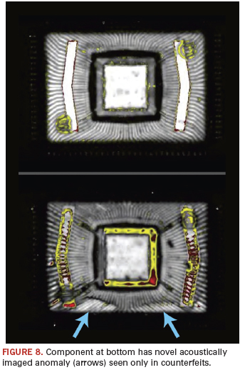
Collaboration between SMT and Sonoscan has resulted in the identification of internal features not previously seen acoustically in components. Figure 8 is the acoustic image of a pair of components. The genuine part at top shows minimal defects. The recycled counterfeit at bottom shows numerous delaminations (red, yellow) on the die paddle and on the tape. But it also shows a surprising feature: two over-bright regions (arrows) near the bottom edge. Something has happened along this edge to make the interface between the mold compound and the lead fingers appear brighter than elsewhere, and the upper edge of this phenomenon is marked by a dark line. Two possible explanations: Sanding may have altered the top edge of the component, causing the returning ultrasonic echoes to bend; or heat may have re-cured or otherwise altered the mold compound in this region, but without creating a gap (delamination), which would be red or yellow. Strange effects seem to occur when components are subjected to heat, mechanical shock and moisture in uncontrolled environments.
This brief article has not covered all of the techniques currently available to identify counterfeit components, but it demonstrates what may be accomplished with the innovative use of technological resources. Since counterfeiters are actively responding to detection methods, new detection methods will continually be developed to keep counterfeit parts out of production.
Dr. Lawrence W. Kessler is president of Sonoscan (sonoscan.com). Thomas Sharpe is vice president of SMT Corp. (smtcorp.com); tsharpe@smtcorp.com.


