A Critique of IPC-A-610E
A master trainer assesses the revised industry guidelines for PCB acceptability.
The visual acceptance criteria for post-assembly soldering and mechanical assembly requirements, IPC-A-610, Acceptability of Electronic Assemblies, was recently “up-reved” as it tries to keep pace with the numerous new component packaging types and other changes to electronics assemblies. The “D” revision, published in 2000, ushered in Pb-free acceptance criteria at the time RoHS standards were put in place. The new “E” revision addresses some more recent technologies since the last revision was published.
The standards task groups made several changes to the Revision “E” document, including but not limited to package-on-package (POP) and leadless device packages, flexible circuits, board-in-board connections and newer style SMT terminations.
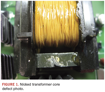
One area where there was a noticeable change is damaged components (found in Section 9 in the new document). Where the previous version held all the information associated with a damaged component termination style under the section on those part types, now all damaged components are in the same section. This will save users time flipping between the various sections. Specifically, sections on damaged transformer, connector and relays are the most significant upgrades.
There have been upgrades to Section 8, the area array section of the standard. This section now deals with differences in both wetting and collapse characteristics of Pb-free solder balls. Since very few area array devices are available with tin solder balls, this is a welcome upgrade. While this is a welcome change, users still complain about the lack of detail in this section.
Another device type that has exploded in terms of its usage since the printing of the last version is the leadless device package. These are addressed in the new revision, also in Section 8. While the revision offers expanded inspection criteria, it does not go far enough in defining the criteria for the myriad different package types available today.
One of the other changes made to this version is the organization of terminals as found in Section 6. For each terminal type, an easy-to-use table guides the user through the plethora of different combinations of different terminal types and their acceptance criteria.
Lead cutting into solder is fully explained with clear photos for through-hole devices in this new revision – a welcome change, as this is an area of confusion among users that should be put to rest. The new photos leave no ambiguity as to where a lead can or cannot be cut vis-a-vis the solder fillet.
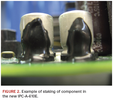
In Section 8, photographs and further explanations help clarify how staking adhesives can be used when mechanically securing components to the board. Section 8 also deals with leadless device terminations, flattened post terminations, as well as other specialized SMT connections.
Flex circuitry criteria for damage, flex stiffeners, soldering flex to flex and flex to PCBs are a welcome upgrade.
Some training organizations have commented that the new standard more closely parallels existing IPC training materials. As my colleague Norman Mier observes, “The new IPC-A-610 format allows for enhanced references that I am sure will improve the training and, more importantly, the comprehension and usage of this important tool for the factory floor.” Training materials for IPC-A-610E are slated to be released in late summer or early fall. In the meantime, students can be certified to the “D” revision and can recertify to “E” in the future.
A free fact sheet and a redlined version highlighting the changes to the document are available from the IPC website.


Bob Wettermann is president of BEST Inc. (solder.net); bwet@solder.net.


