Reflow AI - Before there was Artificial Intelligence
AI is now helping engineers tame the “black art” of SMT reflow by optimizing oven recipes and process decisions.
Artificial intelligence is a hot topic in many industries. The technology suggests we can make better decisions, increase our productivity and discover information that we previously couldn’t find. Recently, SMTA (Surface Mount Technology Association) implemented an AI program named MAX that helps engineers find information on the surface mount process and defects. For example, if you want to know about void mitigation in thermal pads or the best method of cleaning a PCB, you can ask MAX, and it will give you an overview of the process and a list of papers in the SMTA technical library. Programs like MAX dive into the text of papers instead of just looking at keywords and the title.
I recently asked MAX to introduce itself, and here is the reply:
Hey there! I’m Max, your AI assistant from the Surface Mount Technology Association (SMTA). I’m here to help you with anything related to electronics assembly, surface mount technology, process troubleshooting, industry standards, upcoming events and more. Whether you’re deep into SMT production, just starting out or curious about the field, I’ve got your back.
I then asked MAX, “How does AI affect the SMT process?” and it gave me a detailed overview with numerous references.
Before we discuss AI in solder reflow, let’s look at how the solder reflow interacts with the rest of the surface mount process.
Once a surface mount board is designed and components are specified, the process requires that numerous steps be performed correctly to be successful. These steps include screen printing, pick-and-place and reflow. Classic analysis of the SMT process says that 64% of the defects can be attributed to screen printing, 15% to pick-and-place, 15% to reflow and 6% to poor components; but we know that if any single step is wrong, the whole process fails. Additionally, if any step isn’t “on target,” the final product can contain a significant number of defects. People generally understand components, screen printing (Thank you, Chrys Shea), and the pick-and-place process, but reflow is a black art that happens in the big box (oven). The thermal requirements vary by solder paste composition and board and are further complicated because heat transfer to the board varies with oven length, number of zones and oven efficiency.
The primary goal of reflow is to melt solder and produce strong joints with minimal voiding while avoiding damage to components or the PCB. Therefore, for reflow to work, we need the correct thermal profile, and then we find a set of oven parameters that produce it.
Which Thermal Profile?
The correct thermal profile for solder reflow varies with the solder type, paste manufacturer, board density and, sometimes, additional requirements based on the maximum component temperature. A typical thermal profile consists of 6 parts, as shown in Table 1.
Table 1. Typical Thermal Profile Parameters for Eutectic and SAC Solder Alloys Used in SMT Reflow Processes
The type of solder determines the required profile because it sets the temperature needed to melt the solder (liquidus). For example, SAC305 melts at 221°C and requires a peak temperature of about 240°C, while eutectic tin lead melts at 183°C and requires a peak temperature of about 220°C. (Bismuth-containing solder is even lower, with a melting point of 138°C.
The peak temperature of the profile is usually consistent between paste manufacturers because the melting point of the alloy doesn’t change, but the other portions of the profile, such as ramp rates and soak time/temperature, are dependent on the flux formulation. Karl Seelig, formerly of AIM Solder, provided the information (Figure 1) about the constituents of solder paste flux and said that the specific soak time and temperature need to be optimized for the resins, activators, etc., of the individual paste manufacturer.

Figure 1. Solder paste flux generic make-up (courtesy Karl Seelig).
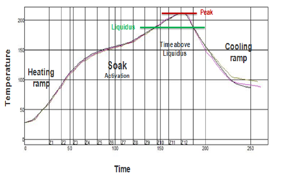
Figure 2. Example reflow temperature curve illustrating the stages required to properly melt solder and form reliable joints.
Heating ramps are important to minimize product movement and solder splatter. The soak supplies the energy for flux activation. Cooling ramps affect stress in parts and sometimes the grain structure as well. Additionally, special considerations should be given when void mitigation in thermal pads or temperature limitations for components are needed.
All this is to say that the best place to obtain your thermal profile target is to work with your paste supplier because they know their product and can give you the best advice.
Reflow Oven Settings
This brings us to the actual reflow oven settings – also known as the recipe. Most, if not all, reflow ovens use convection (hot air) to transfer heat to the PCB and components. Therefore, the formula for convection heat transfer is Q = h • A • t • ΔT. Where heat transfer Q is equal to the time in the heat t, times the temperature difference between the gas and product ΔT, and a combination of the surface area and ability of the product to absorb heat h • A.
As process engineers, we can only affect the time and temperature in a reflow oven – belt speed and zone temperature set points. Here comes the dilemma: How do we obtain six thermal parameters with two knobs? Add the fact that reflow ovens come in different lengths, numbers of zones and thermal efficiencies, identifying the best recipe is complicated. Do we use the experience, trial and error or something else?
Something Else
At one time, experience and trial/error were the only ways to develop an acceptable thermal profile. The first step for engineers was to identify an initial recipe that produced a profile close to the required one. Then make guesstimated changes to the zone set points and belt speed to tweak the recipe and quickly obtain the desired thermal profile. Sometimes those changes were hard to determine, especially for new users. In August 2009, Circuits Assembly published an article on how various reflow oven adjustments affected the thermal profile. This article quickly became a classic when it received the highest number of download requests Circuits Assembly had seen in a single year up to that point.
Experienced technologists used an initial recipe based on a product that was close to the same size and mass on a similar oven, but an appropriate recipe was not always available. Some oven manufacturers included default eutectic and SAC recipes with their ovens to help with identifying a suitable initial recipe. Then it took time and resources to fine-tune the recipes for each new product or when there was a change in the thermal target.
Profiling Assistance – Early AI
The previously mentioned “guesstimated” recipe changes depended on the process engineer's skill and experience and could easily take a full day or more to complete. In some cases, experienced oven manufacturers' process engineers were needed to assist. Companies that made profilers began developing software that helped with the “guesstimates.” The one I am most familiar with is the KIC predictive system, where you list the profile requirements, number of reflow zones, zone sizes, belt speed and set points. Then you ran a board with thermocouples attached at critical locations through the oven with your initial recipe and recorded the results. Next, the software would make recommendations for the new set of zone points and belt speed. The engineer could also input their own changes if they didn’t like the predicted recipe, and the software would estimate the results. Additionally, the software was programmed with limits of the possible belt speeds and zone temperatures so it didn’t ask for something that could not be attained by the oven.
The following figures show how it works.
KIC uses the PWI (process window index) as a measure of how the thermal profile fits in the process window, with 0% being the target and +/- 100% being the upper and lower limits. PWIs highlighted in red identify the “out of limits” parameters, and green numbers the “in specification” results.
Step one. This is the result of an initial profile that is not within the thermal specification. The solid lines show the measured profile, and the out-of-specification points are clearly identified by the red numbers in the table. In this case, the reflow process has a total PWI of -250%, meaning it is not within the specification.

Figure 3. Profiling software adjusts oven settings to bring the thermal process within specification limits.
Step two. The predicted set points and belt speed are calculated by the software and shown below.

Figure 4. Example of software-generated reflow oven settings showing predicted zone temperatures and belt speed adjustments to achieve the target thermal profile.
Step three. The predicted results of the changes the software suggests are shown by the dashed line. The predicted PWI is now -46%, and all points are within the process window.

Figure 5. Thermal parameter variation and process window index (PWI) results used to evaluate reflow performance across thermocouple locations.
Step four. Steps two and three are automatically done when a profile is run, but you need to run another profile with the predicted recipe values to confirm the results.
This process saves the engineer a lot of time and eliminates most of the guesswork. Additionally, if the oven were configured to talk with the profiler, the recipe changes could be automatic. This direct handshake saves time and eliminates transcribing errors.
This predictive procedure had some limitations that can be easily worked around because the software treats all profile parameters equally. This means that the software attempts to center every part of the profile in its specified range and can produce some strange results. For example, sometimes the cooling rate requirement moves the peak temperature to the zone before the last one to control the cooling rate. This shortens the effective oven length and lowers the production rate. The workaround is easy – by eliminating the less important cooling rate from the profile requirement, the peak temperature is left in the last zone, and there are more zones available for the other reflow parameters. Whether the cooling rate is critical or important, it can be easily included in the results with a quick change in the profile requirements to see what it is without making an additional run.
As the software evolved, we were allowed to find solutions that maximized throughput (belt speed) or minimized energy usage with the press of a button. But it required that the engineer decide what the initial recipe should be. If a good guess was made, it would only take one or two runs to get an optimized recipe for the board, but if the first guess was poor, it could take multiple runs.
Initial Recipe Assistance
As mentioned earlier, reflow ovens come in different lengths, number of zones and thermal efficiencies; therefore, it presents issues in finding the “important good initial” recipe. One company partnered with ECD to develop profile starting recipes (i.e., specialized default) on each oven, taking into account the required thermal profile and board mass, which was a little extra help for new folks.
To compensate for the different ovens (length, number of zones, and thermal transfer efficiency) KIC added an optional live database for each oven. When you began profiling the software, it asked for board info (size, weight, etc.), which became part of understanding the oven. This allowed the software to learn the oven's characteristics and develop better initial recipes. In some cases, the initial recipe only needed minor adjustments to be optimized.
Reflow AI Today
In the olden days, we didn’t realize that the oven thermal characteristic learning process used by profilers was artificial intelligence. By continually updating its knowledge of the oven's thermal characteristics, it was able to make better decisions. Today’s reflow profiling software can identify good initial recipes and make better recipe-change recommendations based on oven performance and thermal profile requirements. This saves significant time during new product startup or modification to the thermal requirements. Additionally, it continues to find recipes that reduce power requirements while maintaining a good profile, increasing throughput, or lowering changeover times. In some cases, it can find a single recipe that meets the requirements of multiple boards, so changeover times can be eliminated. All this is because AI can continually learn the thermal response of an oven and remember what set points and belt speeds were used in the past.
A form of reflow AI has been available for many years. It has now grown up and become more powerful. MAX tells us that AI is not yet “lights out manufacturing where everything self runs without stopping, but it is positioned as a tool to assist and optimize processes.”
is semi-retired with over 50 years of thermal process experience at Corning, General Electric, Osram-Sylvania, and BTU. He is currently the VP of Technical Programs of the SMTA Carolinas Chapter and President of FCD-Global Services based in North Carolina.
Dimock is a highly rated SMTA instructor with over 75 papers, presentations, webinars, workshops and publications. He has taught numerous SMTA solder reflow classes and participated in the 5-45 Subcommittee for the development of IPC-7801 reflow oven process control standard. Additionally, he wrote the chapter on solder reflow for the Handbook of Electronic Assembly and A Guide to SMTA Certification by Dr. Lasky and Jim Hall.
He received Distinguished Speaker status at SMTA Guadalajara, Mexico, and was a key presenter for the SMTA Jump Start program for new engineers.
He holds an associate degree in mechanical design from Wentworth in Boston and a bachelor's degree in ceramic engineering from the State University of New York (SUNY) at Alfred.


