In a Slump

Before printing, study material characteristics for resistance to slumping.
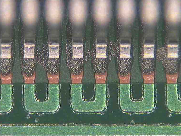
Solder paste slump can and will lead to solder shorts during reflow. FIGURE 1 shows a 0.020"-pitch QFP with wet paste shorts present after placement. The paste may have been present between the pads prior to placement and directly after printing. In this case the printer or SPI should have picked up the faults prior to placement. It is good practice to review the paste products used to understand the degree of slump expected prior to reflow and the highest temperature just before reflow. This will provide insight as to the likelihood of short circuits.

Figure 1. Wet paste shorts, likely caused by excess solder between pads.
In the case of wet shorts, as in the example, it’s not guaranteed this will form a post-reflow short. In a nitrogen soldering environment, for instance, shorts won’t form due to better wetting. It may form on OSP boards in air but not on solder-leveled circuits due to wetting forces. Normally a good quality solder paste will not slump during normal processing; if it does, investigate the performance separate from the process to rule out a material issue.
A good solder paste will be slump-resistant, even when it passes from preheat into reflow, but that is tied to supplier formulations and, in some cases, how products are maintained at the manufacturer. Material problems or batch problems have been seen; incorrect shipping controls or poor storage are also potential issues. It’s worth looking at IPC standards for solder paste tests (J-STD-005) and for solder paste printing inspection criteria (IPC-7527).
These are typical defects shown in the National Physical Laboratory’s interactive assembly and soldering defects database. The database (http://defectsdatabase.npl.co.uk), available to all this publication’s readers, allows engineers to search and view countless defects and solutions, or to submit defects online. To complement the defect of the month, NPL features the “Defect Video of the Month,” presented online by Bob Willis. This describes over 20 different failure modes, many with video examples of the defect occurring in real time.
is with the National Physical Laboratory Industry and Innovation division (npl.co.uk); chris.hunt@npl.co.uk. His column appears monthly.


