01005 Termination Lift
 Inappropriately sized pads can result in excessive solder and, eventually, defects.
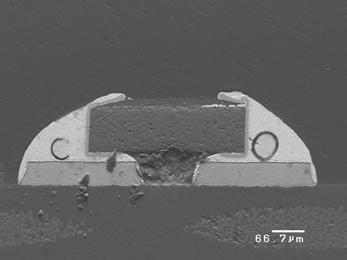
This month we show soldering of 01005 chip resistors from an early project with lead-free assembly. The microsection image in FIGURE 1 shows a few issues, but it’s the circles in both joints that caught my eye. Yes, they are voids before they are unmasked. During sectioning we stopped just before entering the void. Most would have continued a few more micros to remove the thin sliver of solder, which was the wall of the void, to show the void. But everyone has seen voids before!

Figure 1. SEM images show round circles on the joints, excessive pad length and termination lift on top of the resistor.
Now to the important part. The pad size is too large for this small passive device and contributed to the addition of too much paste during printing. The length of the pad was reduced in further trials. During soldering, solder reflowed and wet over the top of the resistor termination. This resulted in lifting of the wraparound termination on both sides.
We have only experienced this on resistors in package sizes of 0201, 01005 and the next level of micro parts. Close examination of parts before assembly from the same batches of resistors did not show termination lift or damage on new parts. Lifting of the termination will most likely be due to contraction of the solder during solidification.
We have presented live process defect clinics at exhibitions all over the world. Many of our Defect of the Month videos are available online at youtube.com/user/mrbobwillis.
is a process engineering consultant; bob@bobwillis.co.uk. His column appears monthly.


