Cleaning Before High-Temperature Aging
 Flux becomes increasingly tenacious the longer it sits on the board.
This month our topic is not so much a defect as something to consider when running environmental tests before any destructive analysis on solder joints. The through-hole joints shown in FIGURES 1 and 2 were soldered with a high-temperature alloy as part of our trials on robotic laser and single point soldering. The amount of flux in high-temperature cored wire tends to be higher, hence more residues after soldering. If sample boards will be exposed to high-temperature storage, in this case 200°C for 1,000 hr., or temperature cycling, clean the residues first. It is much more difficult to clean after this level of aging, and mounting samples in epoxy for microsections is much more difficult.
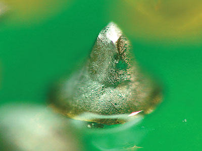
Figure 1. Connector pin soldered with SnAg using robotic laser.
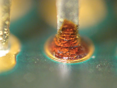
Figure 2. Nonstandard solder mask steps down to the pad, resulting in poor gasketing and an opportunity for process variation.
Cleaning the samples before aging is also good practice if samples will be coated before scanning electron microscope (SEM) assessment.
Figures 1 and 2 are examples of through-hole connectors rated at 260°C. All pins were soldered with SnAg using robotic laser and soldering iron. In each case, results were satisfactory and exceeded IPC Class 3.
We have presented live process defect clinics at exhibitions all over the world. Many of our Defect of the Month videos are available online at youtube.com/user/mrbobwillis.
is a process engineering consultant; bob@bobwillis.co.uk. His column appears monthly


