Tooling May be Out of Sight, but Clues are in Plain View
 When diagnosing print problems, don’t overlook substrate support.
Substrate support is an important, yet often overlooked, element of the screen printing process. Sure, tooling is top of mind when all necessary parts of a new PCB assembly are being developed. But once it’s in the printer way down in the print nest on the table, we tend to forget about the tooling block. I suppose this out-of-sight, out-of-mind mentality is why manufacturers often point to more obvious, visible components of the printing operation as the culprit when the process shows inconsistency. Surely it must be an issue with the squeegee, the stencil or the board fabrication, right? Well, sometimes that’s the case. In many instances, however, a resolution may be as simple as a look at your tooling; something could have changed, or maybe it’s been incorrect from the start.
If the tooling isn’t manufactured properly or has been altered during production, printing inconsistency is the result – either across the board or from board to board. Paste volumes may be noticeably different in various areas of the PCB or panel; one corner may be just fine, and another has too much or too little material. This dynamic could be the first clue tooling is the cause. If the problem were an improperly manufactured stencil, for example, the issues would more likely be consistent across the entire board. Tooling errors can be extremely focused.
Since the tooling is most often only seen at the beginning and end of a product setup, operators and engineers have to use other visual clues to diagnose a potential tooling issue. Obviously, in a perfect world, the tooling specification would be verified with a micrometer and, of course, you hope that’s what your substrate support manufacturer is doing. (Our company’s tolerance spec is 25µm.) Once in production mode, however, with boards flying through the printer every 10 seconds, noticing a problem with tooling will take some investigative work.
If you know what to look for, the signs become fairly simple to recognize and address. The stencil printing process is quite sensitive to pressure changes; any cause of inconsistent pressure during the print stroke will likely reveal itself in material patterns on the stencil. When there is insufficient support or undulation, often ghosting (sometimes referred to as smear), which is a thin film of material, will appear on top of the stencil. The location of the ghosting indicates where there may be tooling problems. When tooling is manufactured correctly, it creates perfect support for the board, and the squeegee blade should not see any deflection; the topography is the same all the way across. Variation in topography due to a manufacturing issue, debris or components falling off into the routed areas or vacuum strength that’s set too high will create certain patterns on the board (FIGURES 1, 2 and 3) that are clues something may be amiss. If the board is raised like a mountain or dips like a valley during the print stroke, ghosting is the most likely material pattern observed on the stencil. When debris or components have fallen into the routed areas or on top of the tooling block, a circle of solder paste – or a hot spot – may be the paste pattern revealed on the stencil topside. And, vacuum strength that’s too high could show itself in a material configuration that aligns with the vacuum holes in the tooling plate.
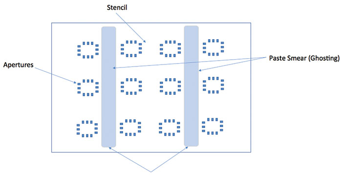
Figure 1. Inadequate tooling support. When dealing with regular patterns of topside smear, review the tooling design to include more tooling support. If the patterns match the vacuum locations, reduce the airflow.
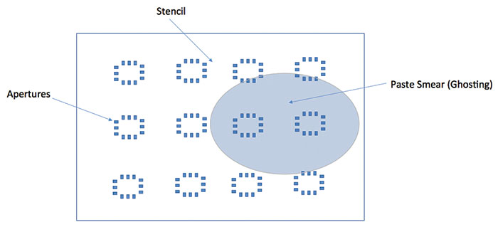
Figure 2. When dealing with a localized area of topside smear, evaluate the tooling plate for debris- or manufacturing-induced coplanarity issues.
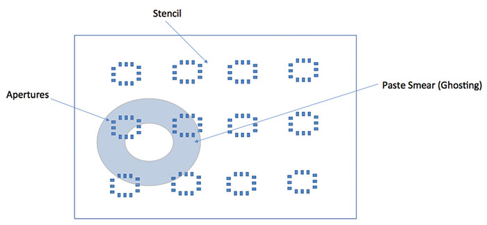
Figure 3. A topside smear with a donut-shaped outline may indicate a localized high spot within the tooling. This could be a manufacturing defect, but more commonly it is caused by dried solder paste or a erroneous component.
Any of these pieces of evidence will help diagnose the possible issues with tooling, most of which are simple to correct. Debris and parts can be cleared, and tolerance issues can be addressed with the tooling manufacturer. Vacuum control is in the hands of the operator. What is not advisable, however, is to wind up the print pressure to “correct” the issue. Unfortunately, this is the approach many line operators take. Increased pressure will, indeed, eliminate ghosting, but other problems will result. Extremely high print pressure can lead to bridging defects, unnatural stencil and squeegee wear and/or damage. In extreme cases, it’s even possible to cold-weld the solder material to the stencil. My advice? Lay off the pressure and figure out the root cause.
The need for tooling adjustments can occur with any type of substrate support, from dedicated tooling to automatic pin systems. Understanding how to diagnose and correct the issues will pay dividends in time, yield and process effectiveness. Your tooling may be out of sight but should be top of mind.
is global applied process engineering manager at ASM Assembly Systems, Printing Solutions Division (asmpt.com); clive.ashmore@asmpt.com. His column appears bimonthly.


