Nobody Makes Through-Hole Joints Anymore, Do They?
 Everyone has an x-ray system for BGAs. Why not use it for through-hole too?
I am often asked about the use of x-ray inspection to investigate issues with surface mount components. Quite naturally, there is always a focus on BGAs, flip-chips, QFNs, etc., where the optically hidden nature of the joints lends those parts to x-ray techniques for analysis. I am rarely asked about through-hole joints, however. Is this because no one uses them anymore? I don’t think so. Indeed, I would venture to suggest there probably are more through-hole joints made today than ever. I am surprised PTH joints do not come up in conversations more frequently because they are obviously hidden joints.
IPC-A-610 guidelines qualify the level of hole fill to be expected within these joints. How else can you nondestructively check during manufacture if these conditions have been met? Are all through-hole joints made perfectly with 100% fill, and never with any issues? Or, as I suspect, is through-hole seen as a great, but slightly less fashionable, technique, and do many not consider an x-ray system can also quickly and simply confirm the quality of these joints? In other words, you already have an x-ray system for BGAs, so why not also get the benefits of its quality control capabilities for through-hole joints?
When using x-ray inspection for PTH joint investigation, you need to image at oblique angled views. If you look at the joints from the top-down only (FIGURE 1), the bulk of the solder down the hole obscures itself, hiding any issues in fill that may have occurred.

Figure 1. Top-down x-ray image of through-hole joints.
It is also worth noting in Figure 1 that the tall through-hole pins do not appear to be standing straight. This is not the case. They are straight in this example, but their appearance here is affected by an artifact of the imaging process. In x-ray inspection, a point source of x-rays from the x-ray tube travels through the sample and hits a large area detector (FIGURE 2). Therefore, any tall, vertical object in the center of the field-of-view (FOV) will appear straight in the image. Any tall objects located away from the center of the FOV, however, cast an elongated shadow at the detector, which appears to suggest the pins are bent in the final image (Figures 1 and 2).

Figure 2. Schematic exaggerating the image distorting effects of tall objects when located away from the center of the FOV and viewed with x-rays.
Taking oblique angled views of through-hole joints (FIGURE 3) can be achieved in two ways: 1) tilting the sample relative to the tube-to-detector axis, with the tube and detector fixed; and 2) keeping the tube fixed, the sample fixed and horizontal, and then tilting the detector.

Figure 3. Oblique angle x-ray image of through-hole joints.
Both approaches will provide the oblique views necessary to analyze PTH joints. The methodology used will depend on the manipulator configuration of the x-ray system. However, using the board tilt method, without always repositioning the region of interest (ROI) into the center of the manipulator tilt axis, will cause the ROI to move farther away from the x-ray tube. As the geometric magnification (GM) of an x-ray image is the ratio of
GM = Distance (x-ray tube focal spot to detector)
Distance (x-ray tube focal spot to sample)
then any movement of the sample, or ROI, away from the x-ray tube will reduce the available image magnification that can be used for analysis. This may not be much of an issue for relatively large through-hole joints, but with shrinking electronics features, especially in other components, this may need to be considered for other inspection applications. Even by moving the ROI to the center of the tilt axis, other areas of the (larger) sample may end up interfering, or clashing, with other aspects of the x-ray system manipulation. Using the detector tilt method does not have these issues, as the sample remains flat with respect to the x-ray tube (Figure 2). Therefore, the sample does not need to move away from the x-ray tube, whatever oblique angle view is selected, and the maximum available geometric magnification is retained.
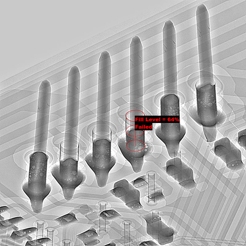
Figure 3 shows simply and clearly the fill is not uniform in this device. You can also see there’s much less image distortion, and the pins now look straight. IPC-A-610 recommends a minimum of 75% fill for through-hole joints. Some x-ray systems will also be able to calculate fill percentage within a through-hole joint (FIGURE 4).

Figure 4. Oblique view of through-hole joints with fill percentage calculation.
Figures 3 and 4 provide a nice example where some joints have 100% fill, and others less. Although it is possible to use the fill percentage calculation on each joint, as I indicated previously about BGA voiding, I suggest to measure when you must, not necessarily always. An operator can be quickly trained to identify what is obviously good and what is obviously bad in terms of fill. They should use the calculations, if available, for the more marginal cases, as shown in Figure 4, where the fill percentage is 64%.
I accept a separate debate exists about defining the acceptable through-hole joint, but you may have to prove expectations of published guidelines to colleagues and customers alike. For through-hole joints, this is something that x-ray inspection can provide quickly, simply and non-destructively. So, for those of you still making through-hole joints (!), an x-ray system is not just for BGAs. It is also for through-holes!
, is an expert in use and analysis of 2D and 3D (CT) x-ray inspection techniques for electronics; dbc@bernard.abel.co.uk.


