News
Installing Flash LEDs on Flex
Flex can save up to 70% in space or weight, but beware of improper bending.
A flex circuit is made from a flexible polymer film laminated to a thin sheet of copper that is etched to produce a circuit pattern. Various configurations include single-sided, double-sided, multilayer and rigid-flex circuits. Figure 1 shows the construction of different types of flex.
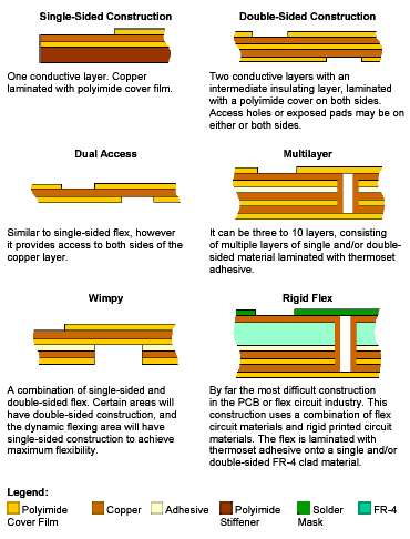 FIGURE 1: Various flex constructions. |
Conventional flex assembly is too soft to support heavy components, thus rigid-flex is the recommended assembly when using LEDs of substantial mass. The solder joint will be very fragile when a bend is near the joint. An accidental bend of the flex close to the solder joint will cause cracks, and thus open circuit failure. To best support these types of LEDs, a rigid-flex hybrid combination is recommended. The hybrid combination consists of rigid boards with the design flexibility of flexible circuits. Rigid-flex boards provide a higher component density and better quality control. Designs can be rigid where support for components is needed, while flex is used for corners and in areas requiring extra space. Figure 2 shows an example of the recommended rigid-flex assembly. Note that when multiple flex layers are used on folding boards, allowance must be made for the inner flexible layer to kink when the board is folded.
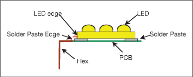 FIGURE 2: Recommended rigid-flex assembly. |
As shown in Figure 3, it is important to balance the copper on both sides of the foil, otherwise it tends to warp during manufacturing and the weaker side of the flex will experience more stress when bent.
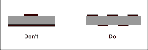 FIGURE 3: Copper spreading on flex. |
Soldering. An appropriate soldering process is needed to form a good solder joint. For example, insufficient heating of the solder paste will cause dry joints. Hand soldering is not recommended, especially for surface-mount LEDs, because it is highly dependent on operator skill to achieve a good joint. Poor process control or operator error can cause overheating of the LED. Reflow soldering is strongly recommended. Figure 4 shows the recommended reflow soldering profile for Agilent’s 1X3 Flash LED, for example, per J-STD-001C.1
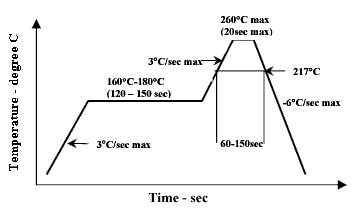 FIGURE 4: Recommended reflow soldering profile for the Agilent 1x3 Flash LED. |
Bending. The bending process usually takes place after all components are mounted on the flex circuit (Figure 5). Some important notes regarding bending flex are:
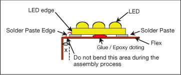 FIGURE 5: Bending process on flex. |
The LED/solder paste edge is the weakest point on copper flex. Any bending at the edge may cause broken solder joints or traces. During the assembly process, do not bend these weak points.
An epoxy coating under the flash LED between the two solder terminals may help increase adhesion to the flex.
Solder pads or mounting holes should be placed at least 2.54 mm from the bend area.
Very thick copper should be avoided on flex layers to minimize stress during bending.
Permanent bend flex tails or tails with a sharp bend near the rigid part should be secured with adhesive.
If the circuit is used for a continuous flex application, plating at the bend area is not recommended.
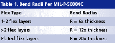
The maximum degree of bend in rotary-draw bending is 180°. Figure 6 shows bend radius definitions. The minimum bend radius is a function of the thickness in the flex area. Table 1 shows recommended bend radii per MIL-P-50884C.2
 FIGURE 6: Bend radius definitions. |
As shown in Figure 7, before bending flex, a jig is needed to support the component on the flex to avoid bending near the solder edge.
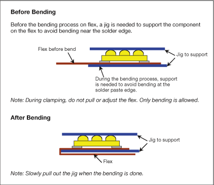 FIGURE 7: A jig supports the component on the flex to avoid bending near the solder edge. |
References
J-STD-001C, Requirements for Soldered Electrical and Electronic Assemblies, January 2004.
MIL-P-50884C, Military Quality and Performance Specification Governing the Manufacture of Flexible and Rigid-Flex Printed Wiring Boards (now inactive).
Shereen Lim is product engineer, Optoelectronics Product Division, Agilent Technologies Inc. (agilent.com); shereen-sy_lim@agilent.com.


