

Current Issue
Designing Flex Circuits For Wearable Electronics
Like the human body, flex boards can work in a variety of positions, but only when the limitations are understood.
Wearable electronic products are emerging as one of the largest growth sectors of the printed circuit industry, and flexible circuitry is showing up in a large majority of these new applications. Since the human body has very few flat, rigid surfaces, standard PCBs can’t just conform to the various body contours and would be very uncomfortable to wear on, or in close proximity to, the body.
This is where flexible circuitry really shines. The ability to flex and bend to follow the contours of the human body makes flexible circuitry the obvious interconnect of choice for many wearable products.
But while flex circuits are able to conform to the many twists and turns of a human body, they still have limitations. If the flex PCB designer is not aware of these limitations, there can be serious reliability issues when the product is in service. It is important, for instance, to know the type of mechanical forces the flex circuit will be subjected to in order to design in features that can withstand those forces. There are many types of wearable electronics and most have their own unique challenges.
Wrist-worn electronics. The surge in popularity of wearable electronics is due in no small part to a plethora of devices worn around the wrist (FIGURE 1). Electronic watches were one of the first wearable electronic products, and it was a natural progression to expand a simple timekeeping device to include much more advanced functionality. Due to the light weight of these devices, they are comfortable and are currently used to monitor everything from general activity levels to sleep cycles. Every day one can see people wearing sports wristbands made by some of the leading fitness companies, in addition to countless other lesser-known brands.
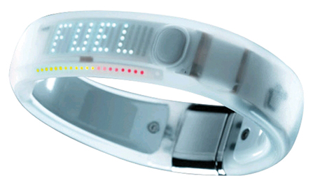
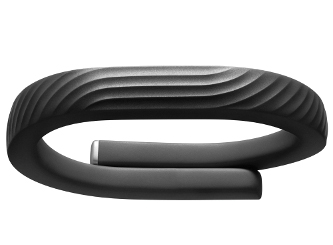
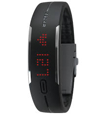
Figure 1. Wrist-worn activity trackers are some of the most popular wearable electronics products.
Because the human hand is larger than the wrist, these devices usually need to be able to separate and expand when putting them on or taking them off. This is where flex circuitry can be incorporated to get electrical signals across flexing areas of the band. The challenge with a flex circuit incorporated into a wristband is that flex circuits don’t like to bend in more than one dimension at any one time. The wristband manufacturer really cannot control how the end-user will remove the device from their wrist. Since most end-users are unaware of the internal workings of the wristband, they may pull and twist the band from their wrist, which can introduce torsional forces. It is important to factor in these torsional forces, along with the single axis-bending forces, when designing the flex and selecting materials.
Another hurdle to overcome in wristband applications is the overmolding process. Flex circuits get very soft and fragile when heated. Heat and pressure from an injection overmolding process can be very damaging to a flex circuit. The flex must be properly supported and the overmolding time and temperature carefully monitored for this to be successful.
Foot-worn sensors. Moving to the other extremities, I have seen many applications for devices and sensors worn on the foot/ankle or in a shoe. These devices are designed to capture everything from the number of steps during an exercise run to diagnosing how irregularities in a person’s stride may cause back/spinal problems. As mentioned, flex circuits do very well when flexed in only one dimension at a given time, so while the bottom of a shoe (inside the shoe of course) can be a hostile environment, flex circuits seem to do a pretty good job and can operate reliably for extended periods of time.
The main hurdle encountered with most of these applications is trying to get data or signals from the flex in the sole of the shoe out to the data-capture electronics. The human ankle is a tough act to follow mechanically, and a flexible circuit does not tolerate the complex movements in multiple axes an ankle tends to serve up. To make connections from a flex circuit inside a shoe to the outside world, I recommend using standard wire with the most elastic insulation available. I have seen some silicone-coated flat cable wiring that seems to hold up pretty well in this application. Obviously, incorporating Bluetooth into the shoe device and skipping past the ankle with RF would be the best choice. One last comment on flexible circuits and its projected lifespan inside a shoe: Even after centuries of refinement, shoes don’t last forever. Don’t ask a flex circuit that is just a few thousands of an inch thick to last forever either.
Wearable baby monitors. What a great idea! New parents always worry about their child when they lay them down to sleep. Audio baby monitors have been around for years but require the baby make enough noise to wake the parents in the event of some type of distress. But what happens if the baby is not able to cry out? That problem is solved with several new products that can be worn by the baby either in clothing or attached to the baby’s leg (FIGURE 2). These new devices are like having your own private nurse standing over the baby all night, monitoring breathing, pulse, movement, etc. If there is a problem, the device sends an alert to the parent’s phone. Since most babies are not running a marathon in their cribs, there are very few mechanical stresses being placed on the flex circuit, so its lifespan in this application should be many years.

Figure 2. Wearable baby monitors are like having one’s own private nurse watching your baby all night long.
Medical sensors. Someone you know been in the hospital recently? One of the first devices typically attached to a patient when admitted to the hospital is a finger worn oximeter. Peeling these widgets apart will reveal a flex circuit wrapping around the end of one’s finger on many of them. Since this is a single axis bending application and usually has a very limited number of bending cycles, flex circuits perform extremely well.
Cardiac monitoring devices are another place flex circuits are found (FIGURE 3). Some of these devices are literally bonded to the patient’s chest with a temporary adhesive, and can monitor heart function for many days at a time. This wearable product allows a patient to return home once stabilized after a cardiac event, rather than staying at the hospital. Data collected by these devices are transmitted to the attending physician for analysis. Flexible circuits inside these devices allow the patient to wear them comfortably for extended periods of time.
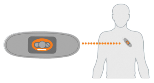
Figure 3. Cardiac monitoring devices can be worn home and will track heart function during daily activities.
Ankle monitors. Have you been a naughty boy or girl? Then you may find yourself strapped with a very undesirable wearable device. Some ankle monitors use flexible circuits to wrap around the perimeter of the ankle to detect if there is an attempt to cut the device off. The length of the flex going around an ankle also gives the flex PCB designer a great place to lay out an antenna to radio the wearer’s location to Big Brother. If discrete wires were used for this application, an enterprising perpetrator could attach jumpers relatively easily to bypass them. Flex circuits, on the other hand, are virtually tamperproof, which makes this a great application, albeit one that you don’t want to be on the wearing end!
Wearable flexible heaters. Flexible heaters (flexible circuits constructed using resistive foil instead of copper) are also finding their niche in the wearable market. Flexible heaters have been incorporated into winter gloves to warm hands and fingers. Flexible heaters have also been used to heat the skin in an injection area to increase circulation and accelerate medication absorption.
Clothing-embedded electronics. It seems that at virtually every electronics show I attend someone asks whether a flex circuit can be incorporated into clothing. The answer is yes; well, maybe. Yes, flex circuits may be put physically into clothing. Better find a way to keep the clothing from becoming soiled, however, because a flex circuit will not tolerate machine washing at all. Having been in the industry for over 30 years, I have unintentionally washed more than a few flex circuits after they were left in one of my pockets. They are usually pretty beat up after a single washing. Remember what I stated earlier about flex circuits performing best when bent in only one dimension at a time? There is much more than one dimension going on inside a washing machine, and the result is a very crumpled flex circuit. Crumpled equals creases in the copper traces, which equals fatigued/work-hardened copper, which equals cracks forming in the conductors, which equals broken electronic clothes. Clothing items that usually do not require washing, such as gloves or coats, may be better candidates for embedded flex circuits than items that will soil quickly and need frequent machine washing.
Pet locating/training devices. What is good for man is also good for man’s best friend. Wearable electronics (electronic collars) have been used for decades for training, and more recently for locating lost pets. Thanks in part to flex circuits embedded into the collar, ranges have been extended to where you can reach out and say “Come!” from miles away. Pet locating collars utilize GPS and cellular networks and can pinpoint a lost pet’s location to within a few feet almost anywhere in the US.
General flex design guidelines for wearable flex circuits. The flex circuit industry does not have a set of hard and fast rules for wearable applications, but following are some features and guidelines that I suggest when designing a wearable flex circuit. Remember that virtually all wearable products would be considered dynamic applications (as opposed to static flex-to-install applications) and should be designed as such.
- Keep copper plating off flexing conductors. This cannot be stressed enough and can be a deal-breaker in many applications. Specifying pads-only or button plating does not mean the conductors will be deposited copper-free. A direct metallization process is required to put down a seed coat of copper in the plated through-holes, and this metallization will also be deposited on the copper surface of all exposed conductors. Even a very thin coating of deposited copper will negate most of the benefits of using annealed base copper. When the thin layer of deposited copper cracks, it will take the annealed base copper with it.
- If the flex circuit will be doing most of its bending in one axis, have the manufacturer lay out the circuits on the panel so that rolling grain direction of the copper runs perpendicular to the bend line.
- If overmolding a flexible circuit, make sure it is securely anchored in the mold so that the hot, high-pressure plastic does not damage or destroy the circuit as it is being injected. In most dynamic applications, be cognizant of the location of the flex circuit neutral bend axis. When a flexible circuit is overmolded, be cognizant of the neutral bend axis of the entire overmolded part. If the flex circuit is skewed too far to the inside or the outside of the overmolding, it can be subjected to extreme tension or compression forces when the part is flexed.
- Thoroughly review the flex design for stress concentration features. It is important to do this review for any flex design, but it is imperative for dynamic applications and critical for dynamic wearable applications. All areas of the flex circuit that will be bent or flexed should be free of stress concentration features. Stress concentration features would include, but not be limited to, changes in circuit thickness or conductor width, coatings and platings, openings in cover material, etc. Any feature that could concentrate mechanical stresses in an isolated area needs to be identified and eliminated. Anyone in this business for an extended period of time will attest to the fact that the vast majority of flexible circuits that fail in service are due to uncorrected stress concentration features.
- Probably the best overall design advice that I can give is to open the lines of communication with your flex circuit manufacturer during the design process. Flex circuit manufacturers have a unique understanding of how flex circuit materials can tolerate diverse conditions and forces. They can help to identify and correct stress concentration features. They may not know everything that will work, but they certainly will know what won’t. With their help, flex can be designed to be worn without being worn out.
is senior application engineer at Flexible Circuit Technologies (flexiblecircuit.com); mark.finstad@flexiblecircuit.com.


