Hybrid Assembly Qualification and Process Control
As case temperature limits drop, tight profiling makes a difference.
Given the electronics industry’s transition to lead-free products and the expiration of many RoHS exemptions, companies continue to use hybrid assembly processes. (Within this article, the term “hybrid” is defined as assemblies using leaded solder and a mixture of Restriction of Hazardous Substance compliant components, non-RoHS and BGAs with lead-free spheres.) Specific industries such as military, aerospace, industrial and medical have lead solder processes designed into their products because of regulatory requirements or by internal decisions to continue assessments of lead-free long-term reliability. These companies are being challenged by the supply chain, which has converted to lead-free components. Some of these companies have performed last-time purchasing buys of leaded components, with some companies choosing to introduce lead-free equivalents while maintaining tin-lead solder requirements. This article focuses on two main themes when implementing or assessing a hybrid manufacturing process, qualification and process control.
Bill of materials review. The first step of the process and product control is to understand the case temperature limits for all components on the bill of materials (BoM). The component with the lowest case temperature will be a focus for the thermal reflow profile because of device integrity. This value will need to be monitored to ensure the reflow profile does not impact the functionality of the component, given the case temperature threshold. If all the case temperatures are rated to 260⁰C, which is commonly specified for lead-free and RoHS-compliant components, then the profile process window will be larger. If the maximum case temperature of a component is 230⁰C, the process window becomes tighter, given lead-free spheres are required to reach temperatures above 220⁰C for ball collapse. A 10⁰ thermal profile delta is more difficult to achieve across an assembly compared to the 40⁰ window of the first example.
Process control. The second step is to establish the thermal oven profile and verify it by using a profile board and thermocouple. Install thermocouples in up to five locations and make sure one or two of the locations are the lead-free sphere of the hybrid components. Also add thermocouples to any locations that may have maximum case temperatures in the 230⁰C range. For more accurate results, make sure the thermocouple is into the lead-free sphere (drilled from the opposite side of the PCB). The profile board should be similar to the hybrid assembly in weight because of thermal mass.
Run the profile board and analyze after the first pass. The key is to ensure the sphere temperature is above 220⁰C to collapse the lead-free sphere. Make sure the reflow temperature is lower than that of any components that may be specified not to exceed 230⁰C. Typically the lead-free component spheres will require temperatures at 225⁰C with a long liquidus for full collapse and complete mixing.
After the thermal profile has been established and verified, controls need to be documented. Equipment change or preventative maintenance will require a validation of the original thermal profile, which is performed using a profile board, given the tight process window of hybrid assemblies. The thermal profile validation should be completed to confirm the parameters (maximum temperatures, ramp, etc.) are acceptable to internal procedures and the solder paste manufacturer’s recommendations.
Assembly qualification and analysis. After the first build of production assemblies, inspection and qualification criteria must be established to verify the lead-free spheres have been mixed and collapsed fully with the tin-lead solder paste. Perform first-article visual and x-ray inspection to confirm collapse and acceptable voiding of tin-lead BGAs. Attention should be paid to the remaining components for visible overheating, solder voiding and warpage.
Secondary steps of the process validation should include a suite of functional testing and assembly verification, thermal stress and cycle testing. The key is to collect reliability data showing the hybrid change is equal to, or better than, the leaded assembly equivalent. The qualification should include destructive analysis or cross-sectioning of the components, which will verify mixing of the tin-lead solder and lead-free spheres. The overall goal of the qualification is to validate the reliability of the hybrid assembly solder joint intermixing. The final step of assembly qualification is overall analysis of the inspection, testing and cross-section data to ensure the hybrid assembly process quality and reliability levels.
FIGURE 1 details hybrid assembly intermixing with a cross-section of a lead-free plastic BGA using tin-lead solder paste. The figure details 100% uniform diffusion of the tin-lead solder with the SAC lead-free alloy. The black lines contained within the sphere are the lead mixing in the solder joint, which is uniform from package to PCB pad. FIGURE 2 details the tin-nickel intermetallic of the hybrid solder joint. The image resulted from a maximum reflow temperature of 225⁰C. The key result is uniform diffusion and collapse of the lead-free BGA spheres when using tin-lead solder paste.
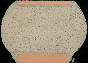
Figure 1. “Hybrid” BGA solder joint, combining a lead-free plastic BGA and tin-lead solder paste.
The key to any hybrid assembly process is the original verification or process control of the thermal profile for the production build, and ongoing checks to verify the thermal profile is within the temperature controls set by the BoM review. Second, a robust product result qualification must be established to ensure the quality output is equal to or better than existing product, and product destructive analysis is conducted to ensure sphere collapse and lead intermixing is present.
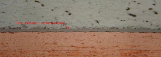
Figure 2. Tin-nickel intermetallic.
References
1. Bob Farrell and Scott Mazur, Green Electronics — Design and Manufacturing, chapter 6; Sammy Shina, ed., McGraw-Hill Education, 2008.
is a manufacturing staff engineer and environmental management representative for Benchmark Electronics New Hampshire Division (bench.com); scott.mazur@bench.com.


