X-ray – Am I Looking in the Right Direction?
 For BGAs it is best to start with a top-down view to look for obvious shorts and over-large voids, and then go to oblique views.
X-ray inspection, at present, requires mainly human analysis to see the flaws. This will be true perhaps unless, or until, artificial intelligence (AI) algorithms provide some alternative solution. However, with so many variables in the x-ray images of assembled boards – the shapes, sizes and density of bumps and joints, the differences in pad solder coverage, the presence of internal copper traces, the overlapping internal and bottom-side components and features, etc. – obtaining an initial training set of exemplars for a ubiquitous AI solution may be tricky.
I suggest this is particularly the case when looking for opens in BGAs. By looking only at a top-down x-ray view, you may miss the fault. In previous columns, I have recommended oblique x-ray views should also be taken to separate the pad and device interfaces from each other and thus give the (human) operator the best chance to spot the open joint or other problem(s). Consider using not only an oblique angle view, but also decide what angle, or angles, are necessary and in which direction(s) around the joint those angle views should be taken.
A greater oblique angle view gives greater separation between the top and bottom joints in the field of view. This helps reveal potential cracks, or separation, between the ball and pad. In contrast, a lower oblique angle view may prevent these failures from being seen. FIGURE 1 shows an example of where using only top-down and insufficient oblique angle views could prevent the identification of a failure, compared with using a larger oblique angle (arrowed). Keep in mind, too, that too great an angle view may also result in adjacent solder balls and features overlapping the problem area you are trying to see (FIGURE 2).
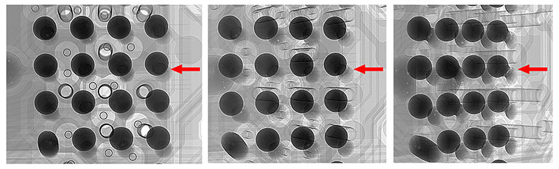
Figure 1. Top-down (l); moderate-angled (c) and large-angled (r) x-ray images of BGA. Crack between ball and pad is only seen at the large oblique view.
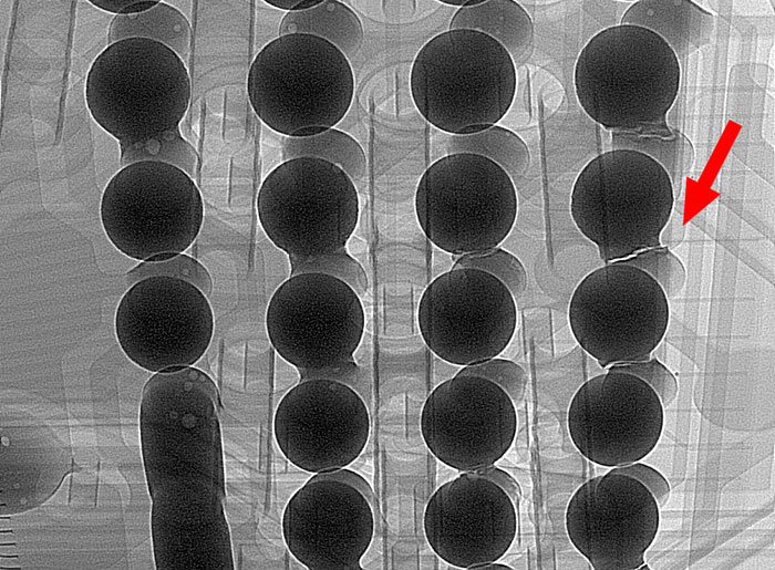
Figure 2. Large oblique view of BGA seen in Figure 1 at a slightly different view orientation. The crack is still seen, but now adjacent solder balls are overlapping, which could prevent seeing the fault.
As all the experts out there will quickly notice, there is so much else wrong with this BGA, it would have been sent to rework long before the crack was spotted. Still, I hope it illustrates my point. Note in this example all the joints are suspect, observable from only using the top-down view, where the presence of “shadows” inside the balls suggests potential issues to the experienced eye. Remember, however, this may be sample-specific. Not all x-ray systems have the same greyscale sensitivity and contrast to permit separation of these subtle variations so clearly. If that is the case, various oblique views become even more important.
Choosing the best oblique angle to use is one thing; selecting which orientation(s) to look at around the joint is another! With 360° to choose from, in some directions the look and shape of all the solder joints may appear similar, masking or hiding the faulty joint. FIGURE 3 shows the large angle oblique view used in Figures 1 and 2 at several other orientations around the joints. The cracks are only visible in a relatively narrow range of orientations. In many other directions the failure cannot be seen at all. In some views, the seemingly large discrepancy and variation between the solder ball shapes in the image may initially suggest a failure, but where instead the natural flow of solder back down the track from specific pad(s), post-reflow, may be the real cause, meaning the joints are actually good. Just because things look different in the image does not necessarily mean there is a problem! For example, in Figure 1, the ball in the bottom left corner has reflowed much more “successfully” compared with the rest of the joints. This is more clearly seen in the oblique views. It looks very different from the rest of the joints, but in this extreme “bad example” this is the “relatively good” joint compared with the rest!
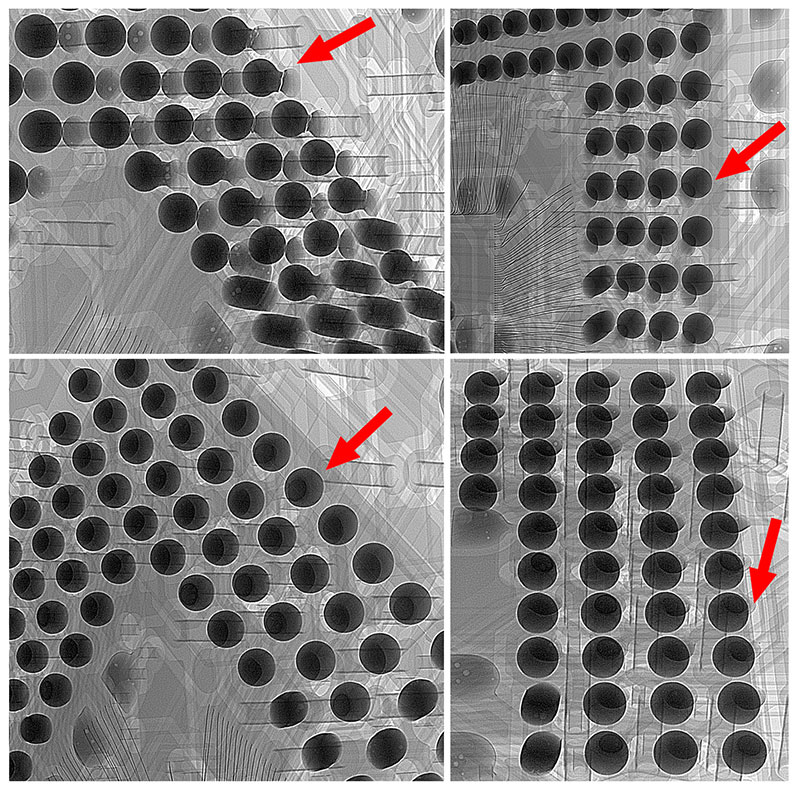
Figure 3. Same angled view but at different view orientations around the sample. The red arrow highlights the solder ball with the crack that is visible from one direction but not from the others.
For BGAs it is best to start with a top-down view to look for obvious shorts and over-large voids, and then go to oblique views. There is no right answer as to which to choose. The important thing is to use several different oblique angle view angles to provide ample, appropriate and optimum joint interface separation and to look at these at various orientations all around the joints to give you the best chance of not missing the problem(s).
Other bottom termination components may be trickier to analyze, as the solder volume and joint shape are more planar, making oblique views helpful but less conclusive, and they usually require a greater oblique angle from the x-ray system to be able to separate and distinguish the interfaces. Again, look for variations, but their presence do not always indicate a bad joint. Even the experienced get it wrong. Use the x-ray system in its optimal way and utilize all its capabilities to ensure the best opportunity of identifying potential problems.
Au.: Images courtesy Peter Koch, Yxlon International.
, is an expert in use and analysis of 2-D and 3-D (CT) x-ray inspection techniques for electronics; dbc@bernard.abel.co.uk.


