

Opens and Shorts in PoP

A tight process can resolve solder sphere issues.
Package-on-package (PoP) technology is very popular in mobile applications such as phones and tablets. Basically, it involves placing one area array package on top of another prior to reflow. In the case of PoP with through-mounted vias, the solder connection forms inside the package, with two spheres reflowing together to form solder columns. FIGURES 1 and 2 demonstrate how solder spheres are visible on the top package (Figure 1), but when reflowed the top package drops and virtually touches the bottom device (Figure 2), making manual inspection of joints impossible to perform. X-ray inspection is the only way of looking nondestructively at the joints.
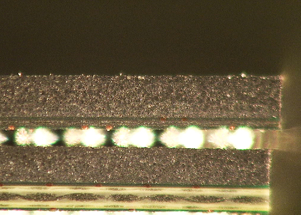
Figure 1. Solder spheres are visible on the top package before reflow
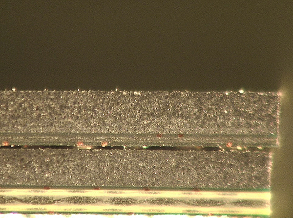
Figure 2. … But after, the top package drops and virtually touches the bottom device, making x-ray the only viable inspection method.
It is possible to experience open joints and shorts with any form of PoP technology unless the process has been correctly defined during new product introduction (NPI). At this step in a successful design/prototype build cycle, collecting data can be very useful for future work. Measurements taken of the package-to-package separation, size of the solder joints in four corners and the total standoff of the package from the PCB can be used during in-process inspection or nondestructive failure analysis. Often this type of data collection is not taken when successful prototypes are built or companies don’t understand the benefits of a well-defined process.
These are typical defects shown in the National Physical Laboratory’s interactive assembly and soldering defects database. The database (http://defectsdatabase.npl.co.uk), available to all this publication’s readers, allows engineers to search and view countless defects and solutions, or to submit defects online. To complement the defect of the month, NPL features the “Defect Video of the Month,” presented online by Bob Willis. This describes over 20 different failure modes, many with video examples of the defect occurring in real time.
is with the National Physical Laboratory Industry and Innovation division (npl.co.uk); chris.hunt@npl.co.uk. His column appears monthly.


