

2005 Articles
Pb-free Standards Update
Several specs have already been updated, and others are undergoing revisions.

The European Union’s RoHS Directive restricting use of six hazardous substances in electrical and electronics equipment will be upon us in 10 months. Lead, in the form of SnPb solder, one of the most basic and well-studied of the six materials impacted by RoHS, is the subject of this article. Changing a solder alloy composition requires additional material and process changes to ensure the manufacture of reliable products. Standardization is essential to understanding and implementing RoHS and other Pb-free restrictions.
Many challenges remain to orderly implementation of Pb-free solder connections. Some challenges are legislative. European governments continue to struggle with the ramifications of their directive. Providing guidance to questions raised by the legislation has caused significant problems. Exemptions are still being considered. The homogeneous level requirement for minimum concentration levels was not defined until late in the process. Many non-EU companies are seemingly unaware of these pending changes and the impacts they will have on the global supply chain. The availability of information continues to increase, but companies still seem unclear on whether the legislation applies to them. This column discusses some of the key standards being revised or developed to clarify requirements for RoHS-compliant materials and processes.
Components. Higher processing temperatures of Pb-free alloys require component suppliers to reclassify moisture sensitive devices as covered in J-STD-020, Moisture/Reflow Classification for Non-hermetic Solid State Surface Mount Devices. J-STD-020 revision C specifies that the temperature for moisture sensitivity level testing be selected according to thickness, volume and mass of the component, and also raises the maximum MSL testing temperature to 260°C (from 250°C).
J-STD-002, Solderability Tests for Component Leads, Terminations, Lugs, Terminals and Wires, is being updated to include testing of Pb-free component termination finishes.
Many component manufacturers have changed component termination finishes from various SnPb alloys to pure tin and high (>95%) tin coatings. These coatings raise potential concerns about tin whiskers, a subject under active study by a number of researchers. To make comparisons between studies, a standardized accelerated tin whisker test is needed. Manufacturers also need test methods for evaluating devices with tin finishes and acceptance criteria. IPC, iNEMI and JEDEC are cooperating to develop methodologies for tin whisker test standardization. In May, JEDEC released JESD22A121, Test Methods for Measuring Tin Whisker Growth on Tin and Tin Alloy Surface Finishes. This standard specifies test conditions for accelerating tin whisker growth and defines how whiskers should be inspected. JEDEC, again with contributions from iNEMI and IPC, is writing a second standard: JESD 201, Environmental Acceptance Requirements for Tin Whisker Susceptibility of Tin and Tin Alloy Surface Finishes. This acceptance specification will be used with the test methods.
Finally, IPC, working jointly with JEDEC and with input from iNEMI, is developing a document titled Current Tin Whiskers Theory and Mitigation Practices Guideline. This guide will help tie all that is known about tin whiskers. The user will be able to go to a single information repository that contains the two standards described above, plus this guideline document. This guideline will be revised as further data come available. The belief is that, with enough data being gathered, the word “mitigation” will change to “elimination” and the title of “guideline” will convert to “specification.” However, the ultimate goal of a specification is not a short-term one.
PCB design. Many companies ask how IPC design standards will address Pb-free soldering, particularly in the area of SMT land patterns. The design standards are not changing, in any fashion, because of Pb-free requirements. Land patterns in the newly released IPC-7351 (superseding IPC-SM-782) meet requirements for surface-mount assembly with either SnPb or Pb-free solders. When IPC-7351 design rules are applied, Pb-free SMT assembly does not differ from eutectic SnPb soldering, and dimensional modifications are not required.
Bare boards. For PCB surface finishes, fabricators have many options, and nearly all will work for Pb-free assemblies. Choice of finish is dependent on the application and preference. Hot-air, Pb-free solder leveling (HASL), immersion tin, immersion silver, organic solderability preservative (OSP) and electroless nickel/immersion gold (ENIG) have all been used successfully in Pb-free assemblies. IPC has published two finish standards, IPC-4552 for specifying ENIG and IPC-4553 to define immersion silver. A third specification, IPC-4554, addressing immersion tin is nearing the final draft, and the fourth standard in the series, IPC-4555 (OSP), is underway. J-STD-003A, Solderability Tests for Printed Boards, is being updated to include testing for Pb-free board finishes.
IPC’s PCB laminate standards also address Pb-free soldering. Again, the higher processing temperatures and the potential impact on the plated through-holes and vias are of concern. Historically, glass transition temperature (Tg) has been used to study thermal robustness. Tg can be evaluated per test methods in IPC-TM-650. The requirements for a specific laminate are called out in the individual specification sheets within IPC-4101, Specification for Base Materials for Rigid and Multilayer Printed Boards.
However, laminate Tg is not necessarily a complete and accurate indicator of Pb-free process compatibility. A better predictor of a laminate’s toughness is needed to show its ability to withstand higher temperatures and longer exposure times. Three more thermal parameters are being proposed and investigated as better predictive indicators of a laminate’s ability to perform in a Pb-free application. These are: coefficient of thermal expansion (CTE), time to delamination (by TMA) and decomposition temperature (Td). A lower CTE, particularly in the thickness dimension, is known to increase PTH reliability. The ability of a laminate to withstand TMA dwells for specified periods of time at 260°, 288° and 300�C is a definitive metric showing the material’s suitability for Pb-free assembly. Td is a newer test that uses thermo gravimetric analysis (TGA) to determine the temperature at which a laminate decomposes to a predetermined 2% or 5% weight loss. Data are being gathered to properly establish Td requirements for Pb-free applications.
To gather data and comments from users for the next revision of IPC-4101, these three metrics are being examined and have been included in proposed specification sheets.
Electrical properties. Changes in PCB materials necessary to improve thermal resistance can alter electrical properties. However subtle the polymeric changes may be for Pb-free assembly, designs that require the maximum electrical performance of traditional epoxy materials will be affected, particularly in high-speed designs. Permittivity or dielectric constant (Dk or _r) as well as dissipation factor or loss tangent (DF or tan _) testing should be run on any new laminate materials designed for Pb-free applications to quantify the need for electrical design adjustments. IPC-4101 provides requirements for the electrical properties of laminates in its specification sheets.
Assembly materials qualification. IPC is revising a number of standards related to assembly materials. Revisions are underway on J-STD-004, Requirements for Soldering Fluxes. IPC-HDBK-005, Guide to Solder Paste Assessment, supports J-STD-005, Requirements for Soldering Pastes, and incorporates details of Pb-free materials. Revision of J-STD-005 is beginning and will include additional Pb-free data. Release is nearing of the latest revision for J-STD-006, Requirements for Electronic Grade Solder Alloys and Fluxed and Non-Fluxed Solid Solders, in which Pb-free alloys are addressed.
Assembly standards. When are IPC standards going to address workmanship requirements for Pb-free? Now. IPC-A-610D and IPC J-STD-001D, released this year, contain requirements for Pb-free solder connections. At the basic level, there are no differences in the solder wetting and fillet requirements. However, some differences in appearance exist. Often, acceptable Pb-free and SnPb connections exhibit similar appearances (Figures 1 and 2) but Pb-free alloys are more likely to have surface roughness (grainy or dull), cooling lines and potentially different wetting coverage. Pb-free often exhibits a greater contact angle, but again, the 90° angle requirement for Pb-free is no different than that for SnPb.
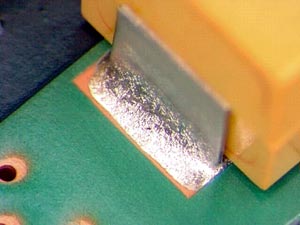 FIGURE 1: SnAgCu solder, water soluble flux.
 |
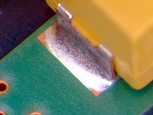 FIGURE 2: SnPb solder, water soluble flux.
 |
Unique requirements acceptable only to Pb-free include fillet lifting – separation of the bottom of the solder and the top of the land – and hot tearing or shrink holes. BGA voiding may also increase, although data do not yet correlate connection failure to voiding.
Pb-free labeling. Existing IPC and JEDEC labeling standards for identification of Pb-free components and assembled boards are being combined. The current labeling standards are JESD97, Standard for Marking, Symbols and Labeling for Pb-free Assemblies and Components, and IPC-1066, Standard for Pb-free Labeling. IPC-1066 not only tracks JESD97, but also includes labeling requirements for halogen-free and conformal coatings.
Thomas D. (Tom) Newton is director, PCB programs, standards and technology, David W. Bergman is vice president of standards technology and international relations, and Jack Crawford is director, certification and assembly technology, at IPC (ipc.org); tomnewton@ipc.org.


Press Releases
- Altus Group Invests in Major Headquarters Expansion to Showcase Complete Turnkey Manufacturing Capability
- ViTrox Americas Welcomes Eric Cruz as Technical Support Engineer
- ECD Strengthens Engineering Team with New Software Development Hire
- ViTrox Americas Welcomes Doug Ennis as Senior Field Applications & Service Engineer