

2005 Articles
Guidelines for Pb-Free Hand Soldering
How to grapple with material, board and component preparation.
Most Pb-free electronics efforts have concentrated on mass or automated assembly and rework processes, and the assorted concerns of transitioning production lines to Pb-free solders. Despite scant attention, good hand soldering techniques are important, even in an automated environment. Many assemblers use hand soldering in low-volume and custom-manufacturing runs.
First-piece soldering, rework and repair operations are routinely performed using manual soldering irons. Now, operators performing hand soldering need to become familiar with the differences between SnPb and Pb-free solders. Pb-free solders require more care and patience during soldering.
Most Pb-free alloys have a higher melting point than SnPb solders. The melting point of eutectic SnPb solder is 183°C. Most popular Pb-free solder alloys have a melting temperature between 215° and 227°C (Table 1).
(For hand soldering, typical Pb-free alloys are SnAgCu and SnCu, based on research performed by various technical consortia such as iNEMI (inemi.org), Soldertec/ITRI1 (lead-free.org) and the IDEALS Program (cordis.lu). Users have the option of using any Pb-free alloy provided that it meets their customer’s hardware requirements.)
Components and boards will be more sensitive to heat-related soldering damage due to the higher melting temperatures of Pb-Free solders. Lucent2 and the Lead-Free Component Focus Group3 have shown that the moisture resistance sensitivity levels of components will increase by two levels, based on IPC/J-STD-020 specifications. Higher soldering temperatures can result in increased board delamination, measling and blistering. For example, measling bridging over 50% of the span between conductors is a defect, per IPC/J-STD-001D.4 Board failure descriptions can be found in J-STD-001D Appendix C and IPC-A-610D.5 To prevent these types of failures, components and boards should be baked prior to soldering to remove any absorbed moisture.
Board finishes should not be a factor in hand soldering. OSP board finishes are prone to a halo around the solder joint. This halo effect is more prominent with Pb-free solders than with SnPb because the former do not wet as well.
Component manufacturers are beginning to provide hardware with alternative finishes. Available finishes include Sn, SnAg, SnCu, SnAgCu, Ni, NiPd and Pd.
For a given part, component manufacturers will not provide several finishes. Market demands will determine the alternative finish of choice. Studies have found no process or reliability incompatibilities between Pb-free solders and Pb-free board finishes.
However, as the technology becomes more mature, possible incompatibilities between Pb-free component finishes and SnPb solders may arise. This is known as “backwards compatibility.” For example, Sn-finish components represent a major reliability concern to some manufacturers. Such components are susceptible to tin whiskers that can cause electrical failures.
Depending upon board size and thermal mass, operators may wish to use a digital controlled hot plate to preheat the board prior to soldering. This practice is performed with SnPb solders, and should continue with Pb-free solders. The higher soldering temperatures necessitate using a digital controlled hot plate. The board should be preheated at 100° to 125°C. Preheating will reduce the thermal gradients within the board during hand soldering.
Hand-Soldering Process Concerns
Solder tip temperature settings. Because of the higher Pb-free alloy melting temperatures, the solder tip temperature has to be set higher. For example, when using the SAC305 solder alloy, the solder tip temperature needs to be set at 343°C, as opposed to 315°C for SnPb.6 The JG-PP/JCAA Lead-Free Soldering Program reported that when building its SAC305 demonstration vehicles, solder tips had to be set at 371° when soldering with SAC. The higher solder tip temperature was attributed to the board’s thermal mass.
Solder tip maintenance. The higher soldering temperature requires that the soldering iron must remain clean and coated with the solder alloy. The higher soldering temperatures can result in the soldering iron tip becoming oxidized if not cleaned and coated. Pb-free solders are more sensitive to the effects of a dirty soldering iron.
To prevent contamination, solder tips used to solder with Pb-free solders must be separated from those used with SnPb solders. Some evidence shows that Pb-free solder joints contaminated with lead are not as reliable as uncontaminated Pb-free solder joints.
Solder tip selection. Choose the proper solder tip size carefully. A tip too small will not provide sufficient heat transfer during soldering. A longer dwell time – the time the soldering iron is in contact with the hardware – is required to promote adequate heat transfer during soldering.
Flux selection. Pb-free solders do not wet as well as SnPb solders. To improve wetting, a more active solder flux may be considered. However, if a more active flux is used, more aggressive cleaning processes will be required. Active fluxes leave residues on hardware, which will promote dendritic growth and poor conformal coat adhesion.
Soldering technique. Due to higher soldering temperatures, the soldering iron has to be removed faster for Pb-free than for SnPb. Pb-free and SnPb solders have different cooling rates and cooling characteristics. Quick solder iron removal prevents the soldering process from disturbing the solder joint and board pads. Lifted pads and lifted fillets are more prominent with Pb-free solders (Figure 1). Icicles (Figure 2) form if the soldering iron is removed too slowly. The size and frequency of solder icicles depends upon the alloy used and the soldering iron temperature setting.
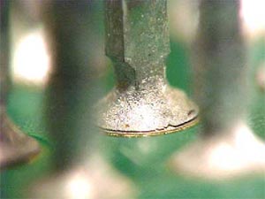 FIGURE 1: Fillet lifting on topside of joint (left) and pad lifting from the surface of laminate. (Courtesy: The Smart Group)
 |
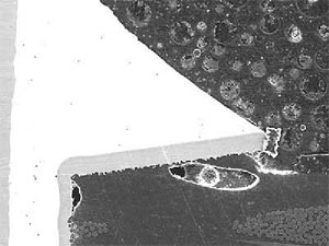 FIGURE 2: Removing the soldering iron too slowly can cause icicles.
 |
The resulting Pb-free solder joints are dull and exhibit a grainy surface (Figure 3). J-STD-001 and IPC-A-610 permit solder joints that appear dull, matte or grainy provided that such appearance is normal for the materials and processes involved.
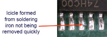 FIGURE 3: Pb-free solder joints are dull and grainy, but can still be acceptable.
 |
Operators will have to be taught the visible differences between SnPb and Pb-free solders. Pb-free solder joints do not exhibit positive wetting. To improve solderability, an operator may increase solder tip temperature or use a more active solder flux. Increasing solder tip temperature may damage the hardware if done indiscriminately. More active solder fluxes may require more aggressive cleaning processes to remove residues. Despite these differences, it is possible to meet IPC Class 3 requirements. The Lead-Free Component Focus Group3 and the JG-PP/JCAA Lead-Free Soldering Program7 proved that it was feasible to meet Class 3 requirements for solder fillet quality, wetting and pad coverage.
References
- Soldertec, “Second European Lead-Free Soldering Technology Roadmap,” February 2003.
- B.T. Vaccaro, R.L. Shook and D.L. Gerlach, “The Impact of Lead-Free Reflow Temperatures on the Moisture Sensitivity Performance of Plastic Surface Mount Packages,” SMTA International, October 2003.
- L. Whiteman, M. Kwoka, J. Cannis, G. O’Brien, D. Hillman, M. Toben and R. Schetty, “Test Results From the Lead-Free Component Focus Group,” SMTA Boston/Nepcon East, June 2002.
- J-STD-001D, “Requirements for Soldered Electrical and Electronic Assemblies,” February 2005.
- IPC-A-610D, “Acceptability of Electronic Assemblies,” February 2005.
- L. Whiteman, “Issues and Solutions to Implementing Lead-Free Soldering,” SMTA Boston/Nepcon East, June 2000.
- L. Campuzano-Contreras, “Joint Group on Pollution Prevention (JGPP)/Joint Council on Aging Aircraft (JCAA) Lead Free Solder Project: Board Assembly,” IPC/JEDEC Lead-Free Soldering Conference, April 2005.
Lee Whiteman is senior manufacturing engineer at ACI (aciusa.org); lwhiteman@aciusa.org. Riley Northam is senior trainer at ACI; rnortham@aciusa.org. For information on the Lead-Free Soldering Training Program, contact info@aciusa.org.


Press Releases
- RBB Welcomes Shawn Myers as Engineering Project Manager
- ECIA’s Market Sentiment Index Average Hits Five-Year High in June Industry Pulse Survey
- Incap Slovakia invests in cleanroom capability to support semiconductor manufacturing requirements
- Orbit Technologies accelerates growth and doubles production capacity with Europlacer iineo placement machine