Conformal Coating Challenges: Detection, Rework and Failure Analysis
A DoE shows optimal removal strategies with various package styles.
Applying conformal coating is the last step in PCB production. Similar to previous production stages, quality assurance measures must be executed. After coating an assembly, proper wetting is primarily visibly checked by manual or automatic means, the latter in cases of high PCB volumes. Transparent coatings are typically fluorescent and can be UV-illuminated. Consequently, coating coverage issues can be revealed using modern camera technology and image processing.1
Although conformal coating presence is beneficial, it may also pose massive challenges during rework and failure analysis (FA). Removal methods include chemical stripping, thermal degradation, micro-abrasive removal and plasma stripping. It is critical to know the coating type prior to removal in order to apply the optimal removal strategy. Sometimes to perform rework, complete coating removal may not be necessary and hence challenges may differ based on the specific locations where removal is needed.
The simplest coatings to remove via stripping solutions are acrylics due to their lack of chemical resistance. However, compatibility issues between the PCB, components and stripping chemicals must be addressed in advance. The other issue with full stripping of a board is the possibility the coating could re-dissolve into the stripper solution. This leads to undesirable coating residue all over the PCB. Hence, a multistep procedure consisting of coating removal followed by cleaning must be done. Sometimes a combination of methods may be needed to remove a particular coating, i.e., in the case of Parylene. Parylene has resistance to heat, cold, moisture and pressure, etc., which makes it appealing to use.2 However, these properties also present distinct challenges for removal. Tetrahydrofuran can be used to soften it, followed by mechanical means of removal. Additional approaches, including microabrasion tool or 193nm excimer lasers with plasma jets, have shown to be effective. These techniques require specific tools and therefore are not cost-effective, however.3
On the other hand, thermal strategies are a low-cost and effective method to remove conformal coating, but may introduce additional failures if the product or component is overheated. Therefore, the temperature selected must be low enough to avoid damage to the component, solder or PCB. Another promising removal method is by mechanical means, which is widely done by microabrasion. The effect of an abrasive material is caused by its three characteristics: shape, hardness and particle size. Individual particles that have edges, such as a block or needle shape, will cut and strip away surface material with greater impact. Spherical-shaped particles do not have cutting edges and are used to “peen” or smooth a surface. The selection of a particular media is dictated by the coating material and pressure of the tool nozzle. Abrasive material containing softer or spherical particles under high pressure may still remove material faster, compared to a blocky abrasive under low pressure. To avoid damage to the solder mask, it is best to use softer particles.4
Yet, there are coatings in which the challenge is not only for rework but also their detection, as some coatings are ultrathin and optically transparent. Ultrathin coatings are becoming popular for high-end, premium devices such as handhelds and wearables, as device slimness is aesthetically pleasing. An example of such coatings is fluoropolymers, which provide an effective anti-moisture migration and anti-corrosion barrier in electronics where traditional conformal coatings are not achievable.5 The low viscosity and low surface tension of these fluids provide excellent wetting and can deliver the fluoropolymer in very tight spaces. The stability of these materials lies in the strength of the C-F bond, which is the strongest single bond with carbon. These properties make fluoropolymers highly stable on the PCB and are hence suited to applications for which long-term stability in humid, temperature-cycling environments is a prerequisite. However, commercialization of fluoropolymer coatings has been limited by the high cost of the raw material and special equipment required to synthesize them. Usually the details of the manufacture of specific fluoropolymers are considered trade secrets, making FA challenging.
Another cost-effective and attractive coating method is plasma deposition. The deposition process itself is simple and can be accomplished with minimal handling or sample preparation in an RF generator. The precursor vapor created in an RF generator is ionized into gas plasma and then deposited onto the surface of the samples. Coating thickness can be controlled by adjusting the length of time the process runs. No further drying or curing of the samples is required.6 Corrosion resistance of plasma-deposited conformal coatings has also been studied by Brooks, et al, where a comparison between uncoated and plasma coated samples clearly showed the circuit damage with the former.7 However, the challenge lies in detection of these coatings before a strategy for rework or FA is undertaken.
The present work demonstrates chemical, thermal and mechanical techniques by which the conformal coating was removed from the PCB, packages or devices mounted on the PCB. Components were removed and placed back on the PCB post-conformal coating removal, and the reworked product was functionally tested. Various metrologies used to detect conformal coating presence and general inspection of the different types of coatings are discussed. The challenges while developing techniques to remove conformal coating from certain packages like quad flat no-leads (QFN) are also addressed. The advantages and disadvantages of using thermal, chemical and mechanical methods of conformal coating removal were evaluated and are reported. A specific FA case, in which detection of ultrathin coatings was a challenge, and ways to overcome it, is described in detail.
Experimental
Optical microscope (OM) inspection and device functionality test prior to conformal coating removal was done to create baseline data. Three different methods were carried out to remove conformal coating: chemical, thermal and mechanical.
Chemical method. Based on the qualitative analysis, technical datasheet and a recommendation from the coating supplier, stripper 1072 was chosen as the chemical to remove the specific coating, as it does not attack solder, copper, silver, gold or nickel plating on the PCB. To perform chemical removal, the coated product was fully immersed into the beaker containing stripper 1072 for 20 min. at room temperature. Immersion times for samples varied from 20 min. to 12 hr. to see the effectiveness of the chemical removal process. To increase the effectiveness of the conformal coating removal, a cotton bud was also used to displace the coating from the sample. Finally, the sample was cleaned thoroughly with isopropyl alcohol (IPA) and dried using a compressed air gun (30 psi).
Thermal method. The sample was placed on a fixture under the vacuum hood. The hot air blower was set to 250oC, facing the top of the coated surface. The temperature of product body measured via thermocouple was about 130oC due to heat dissipation to the ambient environment. A handheld removal tool with a metallic tip was used to remove the coating from the PCB and component surface. The time needed for degradation and removal of coating from the PCB or component surface was around 2 to 3 min.
Mechanical method. To prepare the samples for microabrasion, Cu tape was used to seal the area to prevent abrasives escaping to the surroundings. Various abrasives such as walnut shell, carbo blast, burr blast, and sodium bicarbonate were selected. The tool nozzle was set to a desired pressure (in psi), which was decided based on parameters such as particle shape, size and hardness of abrasive. An initial blast of abrasive was used on the Cu tape before it was sprayed on top of the actual overmold that needed removal. This is because the initial blast of abrasive from the tool nozzle usually comes with a higher pressure before it stabilizes to the desired value. If the initial blast is directed to the sample, it may damage the PCB. The nozzle was swayed constantly during processing. As the bulk of coating was removed, the pressure was brought down further to prevent damage on the PCB. To clean the board post-microabrasion, pressurized air was used. Finally, the Cu tape was removed and the PCB was inspected.
Detection of Conformal Coating. Contact angle and surface energy (SE) measurements were performed using a Data Physics Products OCA35 optical contact angle system. Test conditions included drop size of about 0.50µl for H2O, CH2I2 and glycerol to measure dynamic contact angle (DCA). Contact angle measurements were recorded in degrees.
Qualitative material analysis of the conformal coating material was performed using Thermo Scientific Nicolet 6700 FTIR spectrometer and FEI scanning electron microscope (SEM) equipped with energy-dispersive x-ray spectroscopy (EDX).
Results and Discussion
In FA, specific details on conformal coatings may be proprietary and not readily available. Hence, the first step is to detect any presence of conformal coating. Some coatings are thick and visible by the naked eye, but issues arise when the coating is thin (<micron) and transparent. In those cases, UV inspection can help confirm presence, provided the coating consists of a florescent material. To choose a rework strategy, one can start with qualitative analysis like FTIR to better understand the material. Since most of the coatings are polymer-based, FTIR can provide compositional details. For example, in our case, the coating was thick (> micron), and FTIR suggested it was Poly(n-butylmethacrylate), as shown in the red curve in FIGURE 1. In another similar case, FTIR suggested the coating material to be Poly(ethylacrylate:ST:Acrylamide), as shown in blue curve in Figure 1. Since these coatings covered all the components on the PCB, their removal was necessary to enable rework and FA.
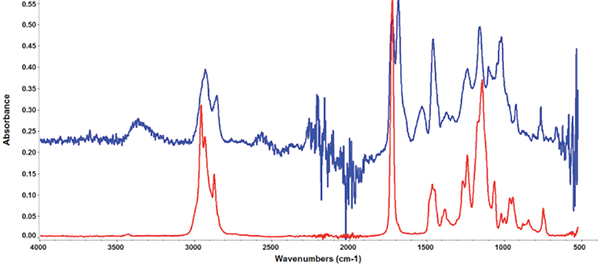
Figure 1. FTIR analysis to get compositional details. Blue curve is Poly(ethylacrylate:ST:Acrylamide), and red is Poly(n-butylmethacrylate).
The first DOE for conformal coating removal is the chemical method, as it does not involve any heat and mechanical energy to the components. It is crucial to choose the correct method to avoid artifacts or failures. Results using stripper 1072 show the removal process is extremely slow and not effective. Optical microscope inspection (FIGURE 2) found that conformal coating could not be removed thoroughly, even after immersion for 12 hr. The results indicated conformal coating exhibits excellent chemical resistance against strong chemicals once fully cured. Consequently, the chemical method for conformal coating removal was not considered, as it has a very long throughput time, and strong chemicals might cause safety concerns.
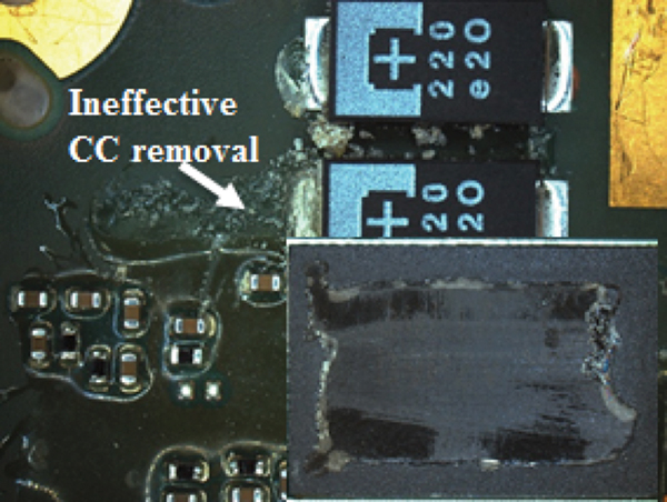
Figure 2. Optical image shows ineffective conformal coating removal using a chemical stripper for 12 hours at room temperature.
Since chemical methodology was not feasible, efforts for conformal coating removal were shifted to thermal methods. For conformal coating removal using thermal methodology, the tools required are easily available (e.g., a hot air gun and handheld tool), and it is unlike mechanical means when expensive tooling may be needed. The experimental data show the low temperature of 130oC on the sample would not melt the solder joint or damage the component functionality. FIGURE 3 shows the area (a) before coating removal and (b) after coating removal using the thermal method.
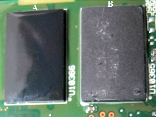
Figure 3. Optical inspection of the package area (A) prior to conformal coating removal and (B) post-removal using thermal method.
Visual inspection and functional test had been carried out before and after the removal process to ensure the thermal removal method did not cause any damage to the product. FIGURE 4 shows the comparison of a failing and passing board after thermal removal. For the failing board, upon functionality check the device didn’t boot up, whereas for the passing board it ran through the entire test sequence and confirmed all the functionality was intact post-removal.
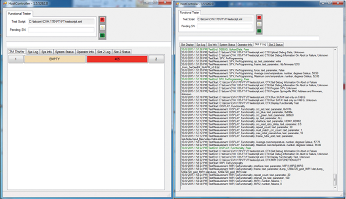
Figure 4. Example of functionality test performed on a failing and passing board pre- and post-conformal coating removal, respectively.
Table 1. Summary of Conformal Coating Removal Using Thermal Method and Component Rework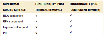
Although thermal removal was successful, a DoE using microabrasion for conformal coating removal was pursued. This was because methods of conformal coating rework that induce minimal thermal impact to the products are usually considered best. FIGURE 5 shows results of microabrasion, where the coating was partially removed from the PCB surface. The coating from (A) in Figure 5 was removed with walnut shell and (B) carbo blast. No visual damage was observed upon OM inspection.
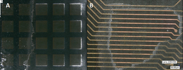
Figure 5. An area on the PCB where microabrasion was performed partially to remove conformal coating.
UV light inspection was performed to confirm complete coating removal from the desired area. FIGURE 6 shows an area of the PCB that has conformal coating and fluoresces under UV light, whereas the area on which coating was removed does not show florescence.
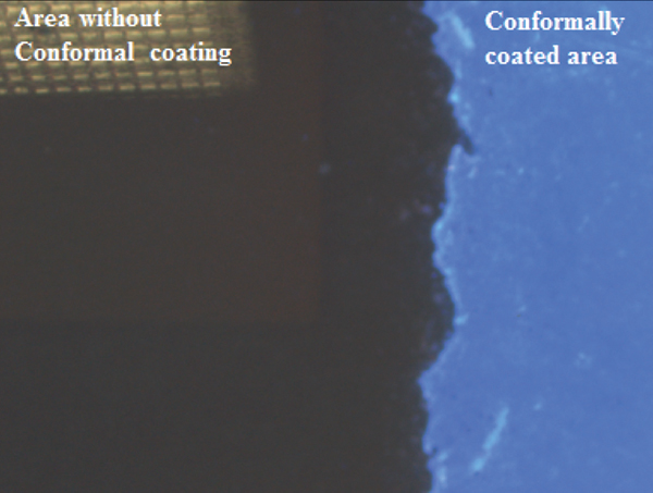
Figure 6. Inspection of the PCB under UV light on which conformal coating was removed partially. The non-fluorescing area shows the effectiveness of the microabrasion process.
Functionality checks on the product post-microabrasion confirmed the success of the microabrasion removal process on the PCB surface. Besides the PCB surface, the DoE included removal of conformal coating on mounted QFN components. Three types of abrasive media were selected for the removal of DoEs, walnut shell, burr blast and carbo blast. DoE results are summarized in TABLE 2. On a control board, the best results were achieved with carbo blast, where no damage was seen on the QFN. With burr blast, the contacts on the sides of QFN were also etched while removing the coating. Walnut shell gave positive results; however, use of this abrasive media is limited due to potential nut allergies. Hence, our microabrasion experiments were conducted mainly with the help of carbo blast.
Table 2. Summary of Conformal Coating Removal on QFN (Abrasive Media)
The functionality check post-abrasion was also positive. With this data, conformal coating from a QFN on a real failing board (FIGURE 7) was removed with the help of carbo blast, followed by package rework and replacement. The board was functional post-rework, proving the QFN was not the root cause.
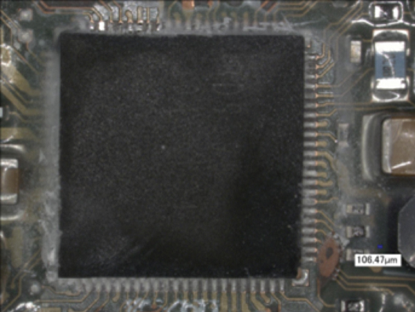
Figure 7. Image of the package (QFN) on which conformal coating was removed by microabrasion.
In some specific cases where conformal coating is extremely thin and cannot be detected by conventional methods such as OM or UV light (Hg, metal halide, black light), an alternate way for detection is highly needed. Knowing the wetting characteristic of the conformal coating is hydrophobic, a water droplet was placed on the PCB surface to detect its presence. A control experiment using the PCB without conformal coating was also performed. The presence of coating was confirmed by evaluating the wetting behavior of a water droplet on the PCB surface. FIGURE 8 shows a water droplet exhibits poor wetting behavior on a hydrophobic surface.1 Usually a contact angle with water greater than 90˚ on a surface is typically defined as a hydrophobic surface.
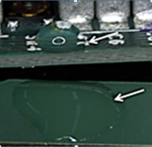
Figure 8. A water droplet placed on the PCB suspected to have conformal coating (top) and a control PCB (bottom) to see different wetting behavior.
SEM/EDX was performed to detect the presence of inorganic moieties on the coating. The data shown in FIGURE 9 suggested the coating may be a fluoropolymer, as evidenced by C and F peaks.
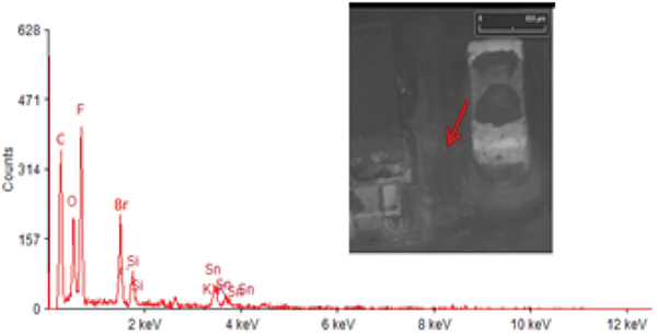
Figure 9. SEM/EDX analysis was done on the PCB suspected to have sub-micron thin conformal coating. The EDX peaks indicate the presence of fluorine.
Experimental results obtained by contact angle and SE measurements of a PCB with fluoropolymer-coated surface are consolidated in TABLE 3. The SE of any solid surface can be calculated using several methods.1,2 We used the geometric SE to understand the type of conformal coating. The simplified geometric equation is shown in Eq. 1, where d represents the disperse component of SE, and p is polar SE.
γ = γd + γp (Eq. 1)
Table 3. Contact Angle and SE Data Comparison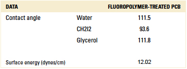
The geometric SE is calculated using two liquids such as water (polar) and dimethyl Di-iodide (non-polar). The SE data comparison on the PCB surface with fluorine polymer vs. untreated surface is shown in FIGURE 10. The plot indicates differences in wetting behavior between these two types of surfaces. Hence, SEM/EDX is a quick, reliable way to confirm if fluoropolymer coating is present. Further, SE and contact angle data when compared to an untreated PCB additionally prove conformal coating is present.
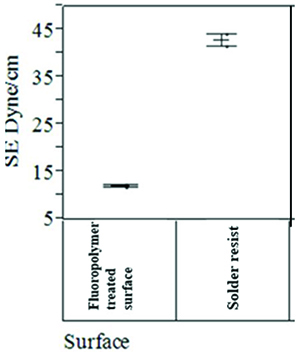
Figure 10. SE comparison of fluorine containing conformal coating and a hydrophobic nm thin film coating on the PCB vs. non-treated PCB surface.
Conclusions
To enable rework and FA, various techniques to remove conformal coating were evaluated. Chemical methodologies were found time-consuming and raise health concerns due to certain hazardous stripping agents. The thermal method is quick and simple for conformal coating removal, but the temperature applied must be precise to avoid damage to the product or component. Successful removal of conformal coating using relatively low temperature has been demonstrated. A mechanical method of microabrasion was found best to remove thick coatings (several microns), provided the abrasive material was carefully selected. The removal process was demonstrated on a control board and unit under test where devices maintained functionality. The demonstration of rework on a QFN component was also shown by microabrasion. In a specific FA case where issues related to thin conformal coating detection were encountered, new detection techniques were proposed.
References
1. G. Caswell, “Coatings and Pottings – Issues and Challenges,” IMAPS, May 2014.
2. R. Kumar, “Ensuring Performance and Reliability of High Temperature Electronics through Thermally Stable Parylene HT at Nano/Micro Levels,” SMTA International Proceedings, September 2015.
3. C. Schmiedel, A. Schmiedel and W. Viol, “Combined Plasma Laser Removal of Parylene Coatings,” International Symposium on Plasma Chemistry Proceedings, July 2009.
4. Comco, comcoinc.com/products/abrasive-media.
5. E. Olson, M. Smith, G. Marszalek and K. Manske, “Ultrathin Fluoropolymer Coatings to Mitigate Damage of Printed Circuit Boards due to Environmental Exposure,” SMTA International Proceedings, September 2015.
6. Y. D. Foote, “Overcoming the Challenges Presented with Automated Selective Conformal Coating of Advanced Electronic Assemblies by Employing Plasma Treatment Technology,” SMTA International, October 2013.
7. A. Brooks, S. Woollard, G. Hennighan and T. V. Werne, “Plasma Polymerization: A Versatile and Attractive Process for Conformal Coating,” SMTA International, October 2012.
Priyanka Dobriyal is materials analysis R&D engineer, Suriyakala Ramalingam, Shu Lee Lim and Anil Kurella is product quality and reliability engineer at Intel (intel.com); priyanka.dobriyal@intel.com.


