

Testing the Mettle of Stencil Foils
Foil alloy does influence paste release, and not all alloys act the same.
In the quest to elevate the stencil printing process from its original black magic art form to the (mostly) science it is today, we’ve developed a number of guidelines to steer us toward success. One of my favorites is the area ratio (AR) calculation. It assumes solder paste sticks to everything equally, and to get a good quality deposit, the force of the paste sticking to the PCB pad must overcome the force of the paste sticking to the stencil when the two separate. We calculate it by dividing the area of the aperture walls by the area of the pad. Fast forward through the algebra, and that boils down to the size of the aperture (diameter if it’s a circle; edge length if it’s a square) divided by four times the foil thickness. The higher the ratio, the more paste is released.
Countless printing experiments on typical Type III SMT solder pastes have shown that if the AR remains above 0.66, we can expect 80% or better paste release on a regular basis, and we’re comfortable with that. Below 0.66, however, release can become pretty unpredictable, and as the ratio approaches 0.50, print quality usually becomes unacceptable as variation skyrockets.
Keeping the area ratio above 0.66 isn’t always easy. Often, components with smaller footprints are getting placed on boards with parts that demand 0.005" or thicker stencil foils. To make matters worse, high population densities often preclude the use of stencil step-downs because there’s no room for them. If an assembler has no choice but to use a 0.005" foil, a 0.012" aperture for a 0.5mm BGA puts the area ratio at 0.6 – scary and unpredictable. If they upsize it to 0.013", then the AR is only at 0.65. Supersize to 0.014" and risk bridging? Well, that gets us to 0.70, but what if the aperture comes in just 0.0005" undersized?
It’s back at 0.67, on the brink of bad printing again. I think of any AR under 0.70 as more of a “Scare-Ya” ratio than an area ratio. They scare me, and they should scare you, too.
But packaging continues to shrink and profitability becomes increasingly difficult, so we try to squeeze every bit of performance we can out of the process. And we’ve got a myriad of options available: squeegee materials, geometries, coatings and vibrations; pressurized print heads; various board support methods and Z-axis separation motions; specialized fluxes and optimized powders; stencil materials and coatings; the list goes on and on.
What’s an engineer to do when faced with all these options? Experiments, what else?
When a leading EMS firm and its stencil supplier wanted to focus on stencil material alone and gauge the impact of foil alloy on paste release, they designed an experiment. They kept every variable in the stencil manufacturing and solder paste printing process as stable as possible, varying only the metal used for the foil.
They tested four different material options:
- A typical stainless steel commonly used in SMT stencils.
- The same stainless steel with electropolishing after cutting.
- Fine grain stainless steel.
- Laser-cut nickel electroplated as a solid sheet.
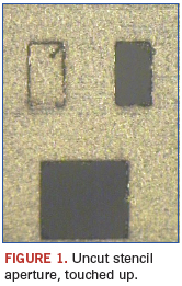
Here’s the short version of how they did it: The foils were all pre-stretched on their frames, and cut on a state-of-the-art fiber optic laser cutting system. Before cutting each stencil, the machines went through a setup routine that included cleaning the optics, focusing the laser beam, and validating the cutter’s performance on a test coupon (Figure 1). Each stencil was cut overnight on sequential nights, following the same setup routine each night, in a climate controlled environment.
The experiment tested the AR range from 0.50 to 0.75 – the Scare-Ya ratios. Different test configurations included all combinations of circular and square pads, both solder mask- and metal-defined, ranging in nominal size from 0.010" to 0.015" with 0.005" foils. Print tests took place in a well-controlled lab with maintained and calibrated equipment. They used their production-approved Type 3 no-clean Pb-free solder paste and printed it at previously optimized parameters. All tests were run sequentially in a single shift.
The paste deposits were measured using white light SPI. About 130,000 measurements were taken during the test.
After the print tests, the stencils were dismantled for further analysis. Each aperture was measured, so the actual area ratios and transfer efficiencies could be calculated and reported. The aperture walls were examined under magnification up to 800X.
And the short version of what they found: Over the area ratio range of approximately 0.5 to 0.75, the best performers were material A, the fine grain stainless steel, and material D, the electropolished stainless steel (Figure 2). Both showed the most desirable transfer efficiencies, releasing 80% of the paste below ARs of 0.60. Material C performed well at approximately 0.66 and higher, suitable for stencil designs that follow the 0.66 rule. Material D was not very forgiving; it did not reach 80% paste release until it approached an AR of 0.7.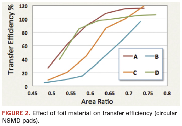
The electropolished apertures provided the most consistent results. They did not necessarily release the most solder paste, but the shallow slope of their response curve indicates they are more robust against small changes in area ratio than the other materials. They also had the lowest standard deviation as a percentage of mean volume, which just happens to be another one of my favorite metrics in stencil printing.
The trends shown for the circular, metal-defined pads were consistent throughout all configurations. The square metal-defined pads and both sets of solder mask-defined pads all followed suit, with nearly identical trend lines. As expected, the square apertures released better than the circular ones.
The repeatability of the data indicates that foil alloy does influence release, and some alloys enable diving a little deeper into the Scare-Ya ratios than others.
What were the identities of materials B and C? What did the aperture walls look like at 800X? What feature identified during microscopy spawned a second study? I can’t give away all the details of the test results right here. The full study will be published later this month at Apex. After its initial publication, it will be available at http://www.sheaengineering.com/downloads.
Chrys Shea is founder of Shea Engineering Services (www.sheaengineering.com); chrys@sheaengineering.com. She wrote this article on behalf of Christopher Associates (www.christopherweb.com).
Ed.: Due to a conversion error, the print version of this article miscalculated the references to 0.012", 0.013" and 0.014" in the third paragraph. We apologize for the confusion.


Press Releases
- Javad EMS Upgrades Through-Hole Soldering Capacity with New SEHO PowerWave System
- Sharpen Your Selective Soldering Skills with Kurtz Ersa's July VERSAFLOW 4/55 Training
- Omron Advances Inspection Technology with NVIDIA Omniverse and Metropolis
- Seika Machinery’s SMI 2026 Webinar Series Continues with Focus on PCB Cleaning Before Solder Paste Printing