Improving SMT Stencil Printer Cycle Time
Changing a stencil printing machine’s conveyor configuration helps make it more efficient.
A well-balanced surface mount line takes into consideration all the equipment comprising it and any indirect factors that affect it. Here we examine stencil printer cycle time (CT).
Internal factors considered for a CT study include conveying time in and out of the machine, stencil and board fiducial recognition, cleaning time, solder paste measurement time, dispensing time, and printing time.
Not all solder pastes have the same rheology, and paste rheology determines a stencil printer’s process parameters. These parameters include squeegee speed, force, attack angle, separation speed (detaching), squeegee material, stencil design, solder paste roll diameter, and stencil cleaning profile, which includes frequency, speed, number of passes, dry, vacuum, wet, and other parameters.
Once process engineers have established the optimum stencil/process parameters to obtain maximum process yield, these elements are locked into the process. From that point, we monitor the results for repeatability. For this reason, changing these parameters to improve the line CT is not a viable option. Also, some products are locked into use of a specific solder paste material, so changing it requires an entire process requalification.
Another approach is to evaluate a machine that performs the process steps most efficiently. In this study, we see how changes in the machine’s conveyor configuration help make the machine more efficient when conveying a given PCB through the process. (The customer process settings remained the same, and boards were processed to calculate total CT.)
Assumptions
- PCBs will already be staged, and no additional time will be added to the machine cycle time. (The upstream and downstream cycle times were not considered.)
- The print stability control (PSC) cycle time will depend on the following factors: squeegee length; the amount of solder transfer to the substrate on every squeegee stroke; paste transfer efficiency; solder paste roll size. (For the purpose of this study, the PSC cycle time was not measured.)
- Stencil fiducials are measured only once. For this reason, no stencil fiducial CT is added to the total cycle time.
Overview
The stencil printer used has staging conveyors in the entrance and exit, with an option to convey the boards in and out of the machine simultaneously. This type of configuration reduces conveying time during processing.
In an overhead view, FIGURE 1 shows how boards are conveyed simultaneously through the stencil printing machine. For this CT optimization, two different PCBs were used, each one with different process settings (TABLE 1).
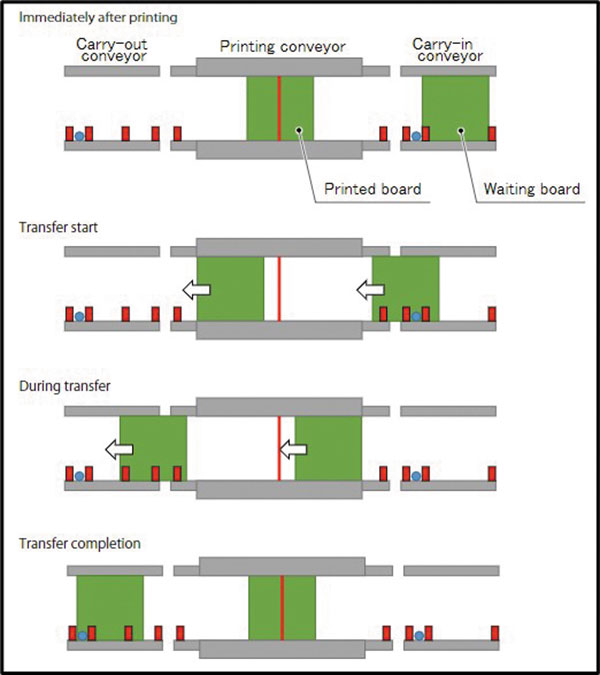
Figure 1. How boards are conveyed simultaneously through the stencil printing machine.
Table 1. Board Process Settings
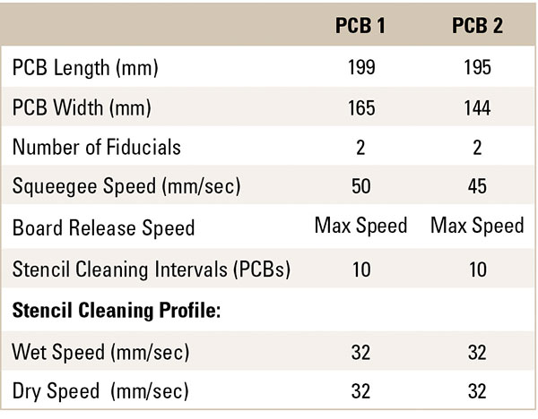
Note: Original print programs were used with our lab machine (Model YSP10) to generate a baseline. Fifty repetitions per board were performed to have sufficient data points from the cleaning cycle time.
Table 2. Baseline (with Standard Conveyor Speed) for Board 1

Table 3. Baseline (with Standard Conveyor Speed) for Board 2

Test 1. To improve cycle time for these two boards, the conveyor speed was increased 50% (TABLES 4 and 5).
Table 4. Test 1 of Board 1

Table 5. Test 1 of Board 2

FIGURE 2 shows the CT difference between the PCBs at standard speed and at a conveyor speed of 50% faster. For board 1, the average CT with cleaning was reduced approximately 2%, and for board 2, 2.5%.
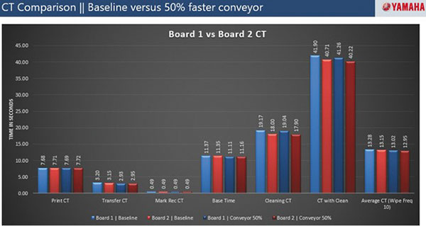
Figure 2. CT difference between PCBs at standard speed and at 50% faster conveyor speed.
Test 2. Machine conveyor mode was configured to move the entrance-staged board once the processed board exited the main conveyor, rather than simultaneously. Note the machine’s conveyors are still staging the boards (TABLES 6 and 7).
Table 6. Test 2 for Board 1

Table 7. Test 2 for Board 2

Test 3. Machine conveyor mode remained with the simultaneous option disabled, and the conveyor speed was increased 50% (TABLES 8 and 9).
Table 8. Test 3 for Board 1

Table 9. Test 3 for Board 2

FIGURE 3 shows the CT difference between boards 1 and 2 at standard speed without simultaneous conveying at standard speed and with 50% faster conveyor speed.
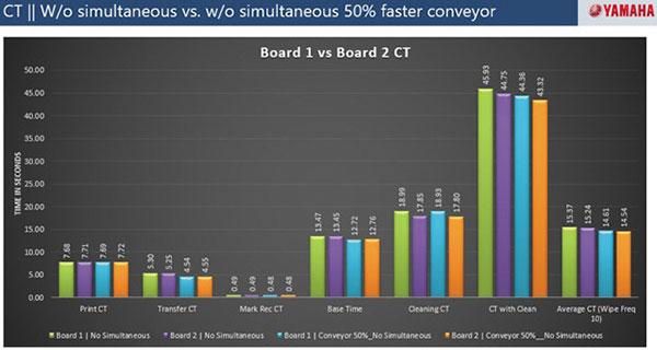
Figure 3. CT difference between boards 1 and 2 at standard speed without simultaneous conveying at standard speed and with 50% faster conveyor speed.
For board 1, the average CT with cleaning was reduced approximately 5%, and for board 2, 4.5%.
In this case, we increased the conveyor speed 50% and used a machine equipped with staging conveyors, with an option to convey the boards simultaneously.
FIGURE 4 shows each board’s CT difference at standard speed, with simultaneous conveying at standard speed and standard speed without simultaneous conveying.
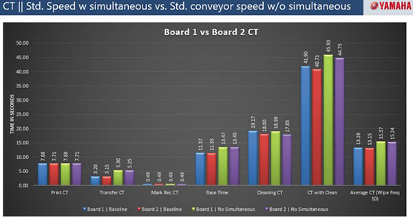
Figure 4. Each board’s CT difference at standard speed, with simultaneous conveying at standard speed and standard speed without simultaneous conveying.
The board’s average CT with cleaning increased approximately 16% when the simultaneous conveying was disabled.
FIGURE 5 shows all CT data for all the conditions tested. The size of the board and the print CT did not impact fiducials recognition CT. The board width dimension impacted the stencil CT.
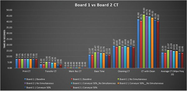
Figure 5. All CT data for all conditions tested.
Significant CT change occurred with the simultaneous conveying option. This impacts the average CT with stencil cleaning.
Conclusion
Solder paste rheology dictates stencil or stencil printing process parameters. Therefore, other machine parameters must be taken into consideration for reduction in cycle time if the solder paste remains the same.
Therefore, any operation that can be done in parallel will impact the overall machine cycle time. This is especially true on the stencil printer, where the majority of factors that affect the CT are interrelated with the solder paste and the board size. In this case, the narrower board has a smaller CT during cleaning.
is product applications manager at Yamaha Motor Corp. (yamaha-motor.com); miguel_colomer@yamaha-motor.com.
Press Releases
- News Zollner Continues to Expand Capabilities in Thailand
- Keiron Printing Technologies Appoints PIT Equipment Services to Support Revolutionary LiFT Technology Adoption
- Surf-Tech Manufacturing Adds New ViTrox V510i AOI to Strengthen Advanced Packaging Inspection
- Altus Supports Cambertronics’ SMT Process Upgrade with Koh Young SPI


