High Accuracy 01005 Placement
Using laser alignment and novel placement force control, accuracy of 50 µm at 4-Sigma is achievable.
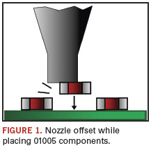
To place 01005 components, the pick process must be very stable. As component spacing will be very narrow, the pickup point of the nozzle must be in the center of the component. Although the component can be picked and aligned successfully when the nozzle is off-center, the nozzle offset (Figure 1) can result in placement offsets, or may interfere with an already-placed neighboring component.
Relatively large 8 mm wide tapes are not suitable for 01005 components. Today, a 4 mm antistatic embossed tape with a 1 mm pitch is quickly becoming standard.
The tape must be accurately positioned for a successful 01005 pick, but the type of packaging is becoming a determining factor for successful pick-and-placement. Feeders in a parallel pick-and-place system have a longer index time without reducing output. The longer index time gives more time to control the index motion. By controlling the tape movement using acceleration and deceleration profiles, the component will remain stable in its cavity. An additional benefit of handling tapes with care is to reduce the effects of static electricity and the amount of paper dust when separating the cover tape from its carrier. Static electricity affects the position in the tape (disappearing, tilting, rotating component, etc.). Paper dust influences the overall quality of the end-product, as it can diminish solderability.
To ensure the complete process is under control, the first step is to pick the component with a controlled force, avoiding possible component damage. Advanced algorithms can take measurements and compare them against a measured “blueprint” to ensure every pick is performed with controlled low forces.
Laser alignment can determine whether a 01005 component is attached to the nozzle on-edge or tombstoned, particularly important for (flatter) resistors (Figure 2). Noncontact positional feedback of components determines position and dimensions by collecting and analyzing the shadows (Figure 3). Laser alignment unit also can detect continuous presence to ensure a component stays in its correct placement position until the nozzle moves down to place it.


A number of tests checked the capability of the component laser alignment unit. A 01005 resistor component was first measured 100 times using the same setting. The results showed a standard deviation of less than 1 µm. Next, over 500 different 01005 resistors were measured with a length deviation of 0.0239 mm and width deviation of 0.0243 mm (both at 3-Sigma over 500 components). Length and width values are slightly larger than component specification, as the measurement on the component outline included leads, which are slightly swelled.
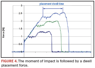
Placement force definition. There are two parts to placement force: the moment of impact, followed immediately by a dwell placement force (Figure 4). For 01005 placement, low, accurate and stable placement force control is crucial. The smaller the area of contact between the nozzle tip and component, the higher the stress on the component. The best placement force of 01005 chips is 2 N or lower (but check component vendor specifications).
A typical conventional placement action comprises the following:
- The nozzle with component moves downward at the maximum allowed speed and decelerates when the component bottom reaches a defined “search” height, which is well defined above the surface of the boards.
- The nozzle with the component then moves down at “search speed” until it has reached a position a little lower than the PCB surface (“over-travel”), to ensure the component is placed.
- The dwell force is controlled by a mechanical spring, which is compressed to the defined length (over-travel length). This is normally defined with reference to the assumed board height.
Most systems use this method, but it does not guarantee successful 01005 placement. A better method is to have no impact force, with the force instead built up toward the required dwell force (also known as static force).
Placement dwell force. On conventional systems, the length of the mechanical spring determines the placement dwell force according to:
Fplacement = Fpretention + zC
Where C is the spring factor (gr/mm) and z is the over-travel length (mm). For 01005 components, both the spring factor and over-travel length should be very small due to the required placement force and dwell force. The dwell force can vary considerably because the actual compression of the spring is influenced by:
- PCB height differences.
- PCB warp.
- PCB stiffness/elasticity (or correct board support).
- Transport parallelism.
- Condition of the mechanical spring.
Reliable placement and consistent dwell force demand the decoupling of all these factors from the placement force control process. Instead of a conventional mechanical spring, we believe an advanced Z-servo mechanism is superior. A closed-loop active placement force control process achieves the required placement dwell and force regardless of component type, PCB type, or condition of PCB, warp and transport system.
During the first part of a placement action, the Z-axis of the placement head moves downward at high speed. When it arrives at the “search zone,” the speed is reduced to the search speed (Figure 5). Then the downward motion continues until contact with the board is detected.
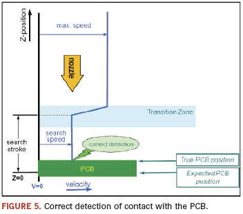
The collision detection mechanism filters out false collision signals, but ensures a component is placed, even if the board was lower than expected (e.g., negative warp). Throughout its lifetime, it records all placements and alerts the operator if behavior may influence placement quality. The collision detection mechanism records a surface map of the PCB, permitting all subsequent placements to be made at higher speed by reducing the search area, even with 3D mounting.
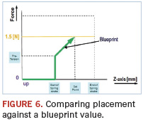
As mentioned, algorithms measure force using the real-time and closed-loop placement mechanism, and compare it against a blueprint value – a placement profile description (Figure 6). When the nozzle rises, the velocity is high enough to break the contact between nozzle tip and component to prevent components from being retained on the nozzle. Monitoring systems check whether the component has detached from the nozzle tip immediately after placement. This quality check filters out behavior that does not meet the blueprint value and warns the operator.
Placement force control test. To ensure quality and reliability of the placement force, measurements were taken in a “worst case” scenario. Measurements were performed on a rigid aluminum substrate. A piezoelectric force sensor was bolted on the board and components were directly picked and placed onto the sensor at default search and collision speed, identical to real production speed. Components are not placed on tape or, as in a real production process, on paste, as these act as a shock absorber.
One test used the same nozzle on several placement heads and placement robots to check for repeatability. The test confirmed that the A-Series placement force control system achieves accurate, stable, and repeatable placement force, even after 20 million picks (Figure 7).
Component pitch is key for 01005 components. For 80 µm component pitch, for example, the minimum accuracy must be 40 µm, even excluding rotational offset.
Pick-and-place suppliers typically define accuracy to IPC-9850 standards, which defines repeatability as the machine accuracy. However, that standard does not represent the true pick-and-place performance in a real production environment. (Repeatability gives the deviation at one location only). Typically, pick-and-place equipment accuracy is influenced by:
- Movement of boards through the machine.
- Measurement of board fiducials or artwork.
- Measurement of the component.
- Placement of the component.
Each step introduces a number of variables that influence accuracy. Each variable will contribute an error that affects the mean offset of the variation from the mean. Per IPC-9850, the specifications for characterizing accuracy are:
- Repeatability for X, Y and Rz deviations, defined at the center of the component.
- CpK 1.33 specification limits for X, Y, and Rz.
This specification limit consists of:
- The mean or average value representing the systematic errors (e.g., calibration residues).
- Repeatability, related to incidental errors that occur in the pick-and-place process, specified at 4-Sigma level.
Based on the criteria above, in company testing, the A-Series achieved accuracy of 50 µm @ 4-Sigma and 40 µm @ 3-Sigma, including rotation.
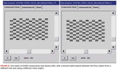
A test placed 72 01005 components between another 72 previously placed, with pitches of 50 µm. The board was thus processed twice by the machine, with the second batch of components picked from a different reel and placed by a different robot. The components were perfectly placed, with no defects (Figure 8).
In recent tests on an AX-501 system, a large contract manufacturer ran 12 boards with 01005 resistors and capacitors, totaling 1152 placements per board.
Components were placed in eight 1 2 x 12 grids, each at 0°, 90°, 180° or 270° and 50 µm or 100 µm pitch (Figure 9).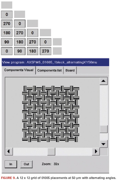
After each three boards were completed, the operator stopped the machine, unloaded the reels, reloaded the reels on a different feeder and started the machine again. After the full 12 boards, all components were correctly picked and placed without any defects.
Satoshi Kataoka is production manager, Assembléon Asia Pacific, and Eric Klaver is commercial product manager, Assembléon (www.assembleon.com); satoshi.kataoka@philips.com.


