How Stencil Manufacturing Methods Impact Precision and Accuracy
Parameters that influence positional accuracy are studied on a number of laser-formed stencils.
For each method used to manufacture stencils, the important parameters are the quality of the equipment, the control over the process to fabricate the stencil, the quality and behavior of the metal during manufacture, the temperature differences during the various processes, and the varying tension on the materials in the different process steps.
The machine used to cut the stencils consists of two systems: the laser and the moving mechanism. The laser must have a small and very stable beam. The size of the beam determines whether very small details can be cut faithfully. If the beam is not stable in size and the main power concentration moves around, the kerf will not be exactly as intended; circular apertures will not be round, and straight wall apertures will have wavy sides (Figure 1).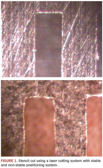
Most lasers produce a stream of high-power pulses to cut through the metal. Early lasers were pulsing at low frequencies, resulting in a scalloped cut when the metal was moved too quickly. Present day lasers employ a much higher pulse frequency, permitting faster cutting speed without resulting in a scalloped cut line.
To verify that the laser beam is stable and produces constant power, close examination of the aperture size, shape and wall is required. With a 40 to 100x microscope, it is easy to see whether the walls of an aperture are properly formed.
Various movement system designs exist. Early systems had a stationary laser beam, while the table holding the metal sheet or stencil frame moved in the X and Y axes. In some later systems, the beam moves in X axis and the table in the Y axis. The next step is to hold the metal stationary and move only the beam in the X and Y axes.
The reduction in mass to be moved makes it easier to increase cutting speed without sacrificing the ability to faithfully reproduce the detailed shapes of the stencil apertures.
In each design it is important that X and Y axes move perpendicularly to each other and that both move in a perfectly straight line (Figure 1). The movement system has to be perfectly calibrated to ensure control over the amount of movement to within a few micrometers. Most laser systems advertise location precision of 5 to 10 µm over a given distance.
Metals. The metal used for laser cutting has typically been stainless steel, type 302 or type 304, produced in a rolling mill. The resulting sheets are very uniform in thickness, but the specified thickness can typically vary by about 12 µm. To improve paste release, a number of post-processes have been tried: for example, electropolishing or chem-polishing, but not always resulting in improvements.
Other metals being introduced include nickel sheets and very fine grain stainless steels. The latter ones in particular have demonstrated significant improvements in the printing process.1
Electroforming. Stencils fabricated using the electroforming (EF) process consist of pure nickel. The EF process starts with a film that represents the aperture pattern to be manufactured. Making the film introduces additional process steps with their inherent possibility of errors, as film material is temperature- and moisture-sensitive. The film image is transferred in a photo process to a mandrel on which a metal layer is grown in an electrochemical process. To get a uniform thickness stencil requires that the chemical actions in the bath are exactly the same over the full area of the stencil. This can be difficult, especially when the aperture density varies greatly. Also, the growth of the metal immediately around an aperture can be faster, resulting in a small ridge or “dam” around the aperture. This dam has been used as a seal between the stencil and pad on the board. However, if this dam is not exactly aligned with the pad or it gets damaged, paste can leak through, which may result in solder balls.
The process also has to be well controlled so that it can be stopped at the proper moment when the sheet has grown to the desired thickness. After that it must be “peeled” off the mandrel without damaging the sheet, and then mounted in a frame.
Tension. When sheets are laser cut, they are typically clamped and tensioned in one direction, or they are cut already mounted in a frame.
If the sheets are mounted in the frame after cutting, the tension in both X and Y directions will often differ from the tension during cutting. The same, but more so, is true for stencils made with the electroforming process.
A stainless steel 125 µm (0.005") stencil manufactured without any stress on the metal and then placed in a frame exerting a stress of 35 Newton/cm (common mesh tension) sees a strain (percentage change in length) of 0.0131%. For a stencil image (or panel image) where apertures are 0.5 m (20") apart, this can cause an error of up to 65 µm (0.0025").
Temperature. Most stencil manufacturers produce stencils in air-conditioned rooms where the temperature is about 20ºC. In small, un-air-conditioned rooms, the temperature can easily vary by 5ºC or more. Similar variations can exist at the location where the stencils are used.
The coefficients of thermal expansion are approximately 17 ppm/ºC for steel and 13 ppm/ºC for nickel. This number indicates the expansion or contraction of the metal in microns per meter for each ºC. For a stencil image (or panel image) where apertures are 0.5 m (20") apart, and the temperature difference between fabricating the stencil and using the stencil is 5ºC, the change in dimension in a steel stencil can be 42 µm (0.0017"). For a nickel stencil it would be about 32 µm (0.0013").
While laser cutting, the hot beam can cause a local temperature rise in the metal that can lead to discoloration (innocent) or even deformation through local expansion of the metal (troublesome). Proper beam control and metal cooling (airflow or liquid cooling) can minimize this problem.
Impacts on Use
For newer components, such as CSPs and very small passive components, the space between pads on the board can be less than 200 µm (0.008").
To prevent significant errors as described above, employ the best stencil manufacturing equipment and practices possible. That also means working in a controlled environment, both at the stencil manufacturer and user locations. To prevent errors due to possible tension differences, it is desirable to cut the stencil while mounted in the frame. In short, as a stencil user it is becoming necessary to know what equipment and what process is used and what checks are made by the stencil manufacturer.
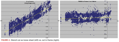
Figure 2 shows an example of one stencil cut from a sheet and then mounted, and another cut in the frame on the same laser. A definite change in the error trend can be observed.
Stencil verification. The simplest way to determine stencil precision is to scan it and determine the location and size of each aperture. Available systems can perform such tests to accuracies of +/-5 µm (0.002") within a few minutes. A computer program can determine the centroid and size of each of the scanned apertures and compare those to the original design. The resulting data can be used for an easy go/no-go determination, or to perform statistical analysis.
The new scanned laser-cut stencil may have remaining loose particulate in some of the apertures. This interferes with the centroid and area calculation, but can easily be recognized and therefore excluded from the results (Figure 3).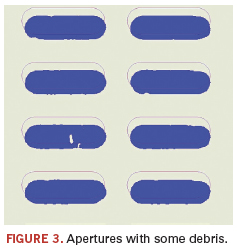
A large stencil (about 460 x 300 mm) with about 21,000 apertures was selected for these tests. Stencils were measured using a well-calibrated scanner (ScanCheck) with a resolution of 6,000 pixels per inch (12,000 with interpolation). The resulting numbers were then compared to the cutting data and errors beyond a given specification presented. All data collected can be exported for further analysis, as is done here. For this analysis, only the location errors along the long stencil axis are used.
Comparative Measurements
For comparison purposes, a number of stencils were produced using different methods, machines and processes. These stencils were produced using commonly available laser-cutting and electroforming production methods. Four different laser system brands, for a total of seven different types of machines, were selected. Of these stencils, five were produced both as sheets and in a frame and two cut in a frame, for a total of 13 laser cut stencils and one electroformed stencil.
The stencils were produced in several different commercial facilities, and environmental conditions were not recorded; therefore, a temperature effect cannot be established separately from the machine accuracy and tension effects.
A specification of +/-10 µm was used, and for each stencil, the extent and distribution of the location errors were calculated. This aforementioned specification limit is a commonly used value for allowable tolerance by many large EMS companies. The value of Cp indicates how often this distribution of the data fits between the specification limits (Figure 4). For these very large and complicated stencils, only one showed a Cp value greater than 1 (Figure 5). In the individual graphs, the short green bars represent the three sigma limits. At those points the error rate is 2,750 ppm. Of course, Six Sigma would be more desirable, where the error rate would be only 0.002 ppm.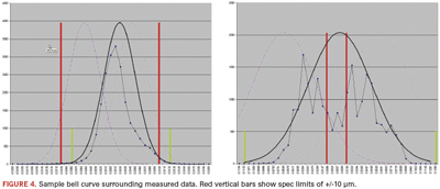
As the stencil can be shifted and aligned to the board in the printer, the Cpk value, which uses the worst half of the distribution and the deviation of the mean from the center of the specification, has not been determined.
Results. The resulting Cp values for the whole group of stencils are shown in Figure 5. Yellow bars show the Cp values for stencils cut as loose sheets, and blue bars show the range for stencils cut in the frame. For the measured apertures, the error range (brown bars) varies from 35 to 185 µm (0.0014"to 0.0073").
The data show a noticeable grouping based on the chosen manufacturing techniques. In general, stencils cut in a mounted frame show significantly higher aperture positional accuracy than stencils cut as loose sheets and subsequently mounted into a frame. 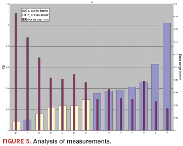
Figure 6 shows the distribution of the data for a stencil cut in the frame and as a sheet using the same laser. The noticeable change in the spread of the data shows the result of the change in tension while cutting the stencil versus the tension after the stencil has been mounted in a frame.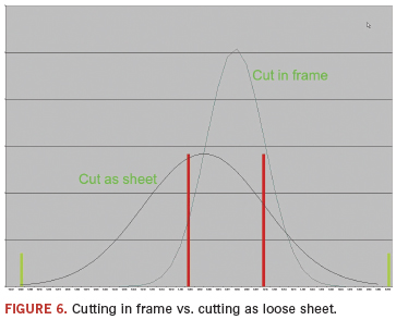
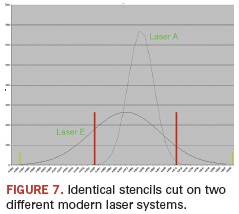
Another factor for the change in positional accuracy is the choice of laser cutting system. In general, we can observe that most newer systems (fewer than three years old) provide a higher positional accuracy compared to the older systems (three to 15 years old). However, even among new laser systems we can observe a significant difference in aperture positioning accuracy between different laser systems. These differences are probably related to system architecture and calibration methods used. Figure 7 shows the change in the spread of the data for two stencils cut in the frame on two different laser systems.
Conclusion
When printing on a board with components that have large pads and large spaces between pads, a significant alignment error between the stencil apertures and board pads may not cause serious issues. It is like a form of overprinting, and many solders, in their molten state, will wick back onto the pad.
However, many of today’s boards have tiny parts with very small and closely spaced pads where such errors might cause bridging. Also, Pb-free solder does not spread as well as Pb-bearing solder. Therefore, the size of the errors encountered in several of these stencil samples will lead to unacceptable levels of production errors.
For a stencil with optimum aperture positioning accuracy, we can conclude that laser cutting shows better results than photo-based processes; stencils cut in a frame show very little distortion, and stencils cut on modern lasers show significantly better positioning accuracy.
Note that additional printing errors can come from, among others, low mesh tension, inadequate squeegee pressure or insufficient board support.
Acknowledgments
The authors thank Florian Roick of LPKF Laser & Electronics, Mike Scimeca of FCT Assembly and Frank Kurisu of Solder Mask Inc. for their kind contributions to this article.
References
1. Robert F. Dervaes, Jeff Poulos and Scott Williams, “Conquering SMT Stencil Printing Challenges with Today’s Miniature Components,” Global SMT & Packaging, April 2009.
Ed. This article was first published at the SMTA Pan Pac Conference in January 2011 and is republished here with permission of the authors.
Ahne Oosterhof is founder of Oosterhof Consulting; ahne@oosterhof.com. Stephan Schmidt is general manager of LPKF Laser & Electronics (www.lpkfusa.com); sschmidt@lpkfusa.com.


