

Robust Tacking Material Technology to Reduce Tool and Fixturing Complexity in Power Module Assembly
A solution for flux-free formic acid reflow?
Growing performance demands for power electronics systems, driven by rapid advancements in application areas such as electric vehicle (EV) technology, present challenges for module design.1 With increased junction temperatures, current densities and complex thermal packaging solutions, engineers must improve reliability through the design phase and material selection process. This requires constant optimization of the power module design and process flow to produce effective and reliable solutions. For successful power electronics applications, however, the production process is equally as critical as the design to achieve the required quality and cost target. One key element is the use of tooling as it affects the design (e.g., distance and tolerances between dies) and manufacturing processes (cycle time, quality and costs). Process advancements of high-quality reflow techniques with vacuum and formic acid have proven effective to achieve reliability targets,2,3 but the focus is shifting toward scalability and efficiency to bring up production levels that meet the aggressive needs for these new applications. Due to the constantly increasing power densities in power modules, soldering processes that avoid use of additional flux are becoming more important. The upfront cost in development of processes, unique equipment, and dedicated fixturing to achieve quality is a growing concern that presents both a significant financial burden as well as a time-to-market impact for power module manufacturers introducing new designs.
Vacuum reflow with formic acid reducing atmosphere has proven to be an effective technique to achieve high quality, with solder preforms with a void rate under 1%.4 With this technique, material cleanliness is critical, and any residue that remains after the assembly process must be removed to prevent performance issues such as increased leakage current or corrosion.3
A no-flux reflow process can mitigate issues due to residue and avoid additional cleaning steps that add process time and cost.
Solder Reflow Tooling Requirements
Improper alignment of the solder preform during assembly can lead to latent defects in the solder joint, including tilt, mechanical stress, uneven heat transfer and thermal stress, resulting in delamination failures that reduce lifecycle reliability. To overcome this, designers typically develop sophisticated placement and alignment equipment upfront in the new product introduction process to prevent movement and misalignment during manufacturing assembly. These elaborate fixturing systems require focused design and development and create many design for manufacturing (DfM) constraints for the power module and assembly process, such as the use of advanced materials to mitigate the effects of CTE.
The design and sourcing effort not only comes at a premium cost, but also impacts the lead time and market introduction of new power module projects. Last, these tooling and fixturing systems tend to be unique for a given module product or assembly sequence, with little opportunity for reuse, impacting the return on the upfront capital investment, particularly for manufacturers with limited production capacity and high mix in product configurations. FIGURE 1 summarizes the typical power module assembly and reflow sequence.
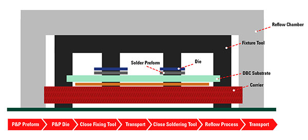
Figure 1. Typical power module assembly sequence.
Tooling Alternative
To overcome this manufacturing constraint, a novel material technology has been developed for solder preform assembly to enable precise placement without dedicated tooling and fixturing equipment. This material, when dispensed during assembly, provides robust tackiness to maintain consistent alignment of the solder preform and assembly components, thus preventing uneven stress distribution or thermal concentrations. FIGURE 2 illustrates this tool-free concept for a typical power module assembly, specifically with the tacking material dispensed at the die and direct bond copper (DBC) substrate/baseplate solder preform interfaces.
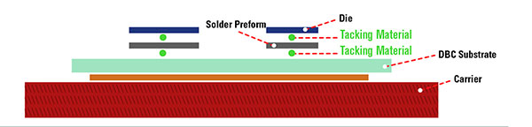
FIGURE 2. Tacking material application for power modules.
The tacking material used in this application contains no fluxing properties; instead, it is completely consumed during the reflow process with no remaining residue, avoiding the need for post-process cleaning steps and making it a solution for flux-free formic acid reflow techniques that are widely used in power module production.
Tacking Material Assessment
First, the robustness of the attachment properties for the novel material were analyzed using a conventional tack testing method commonly used for electronics assembly materials:
- Circular deposits of material printed
- Measurements every two hours over a 24 hr. period
- 20% relative humidity, constant.
The novel tacking material was tested against a conventional tacky flux and isopropyl alcohol (IPA) variants as a baseline. As demonstrated in FIGURE 3, the novel material shows high tack strength even when compared to a typical solder paste. The high tack is maintained over time, demonstrating consistent properties over a long working time. The IPA solutions tested in this setup exhibited a relatively low tack strength and significant degradation over a short period of time, thus reducing the viability of IPA as a tool-free material alternative.
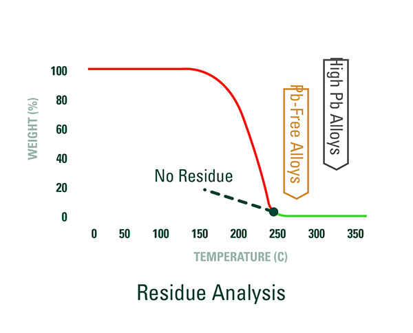
FIGURE 3. Tack testing results.
Residue. To further evaluate the viability of the tacking material, a series of tests were performed to simulate a typical power module reflow process leveraging vacuum and formic acid. First, a TGA was performed to analyze the potential residual components after the material had reached the target processing temperature. As shown in FIGURE 4, the tacking material was completely consumed with zero weight % after exposure to a temperature of approximately 230°C. With typical soldering alloys for power module assemblies including SAC, SnSb or high-Pb, the risk of contamination from residue during a flux-free soldering process is low, as the processing temperatures for these alloys are generally much higher than the curve captured from the TGA.
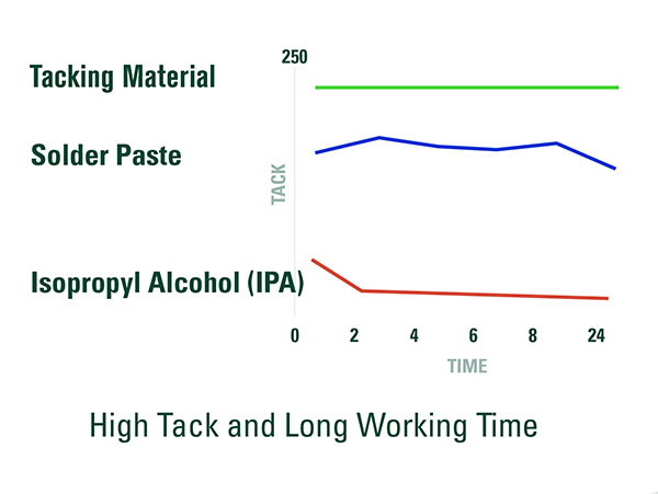
FIGURE 4. TGA analysis of tacking material.
To further evaluate the risk of residue contamination, the tacking material was evaluated against a typical analysis suite for electronics assembly cleanliness through a collaboration with Zestron. The scope of this testing included surface analysis with ion chromatography, energy dispersive x-ray (EDX) analysis, and Fourier-transform infrared spectroscopy (FTIR) analysis, and samples were generated for a die-attach application with solder preforms, dies and DBC. For a baseline comparison, samples produced with the tacking material were compared to samples produced with no tacking material under the same formic acid reflow process. These samples were also compared to “bare” assembly components (before reflow). FIGURE 5 provides a summary of surface analysis results, focusing on the presence of typical contaminants. The following samples were analyzed:
- Bare DBC, before reflow
- Bare DBC, reflow only, no solder
- DBC with tacking material, no solder
- DBC with tacking material, soldered
- DBC and die with tacking material, soldered.
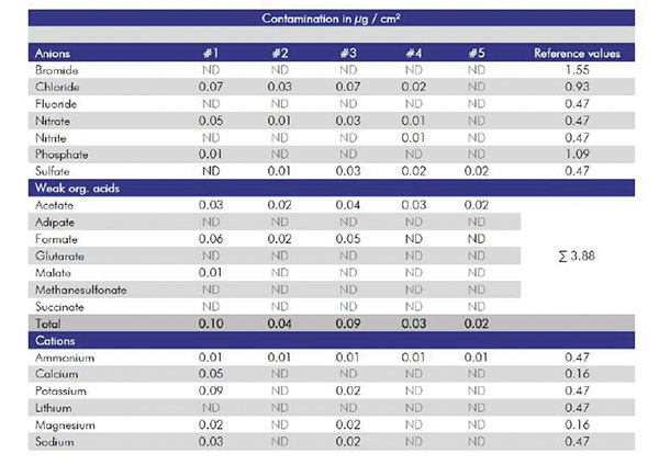
FIGURE 5. Contamination analysis.
Based on this summary table, levels of typical contaminants were well within control limits for all samples and demonstrated no contamination. In addition, there was no significant difference in levels measured with the tacking material samples compared to the baseline samples.
Further, FTIR and EDX analysis of the samples with tacking material also demonstrated consistent results when compared to the baseline results in FIGURES 6 and 7, respectively.
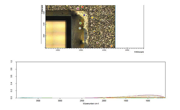
FIGURE 6. FTIR analysis: No evidence of contamination.
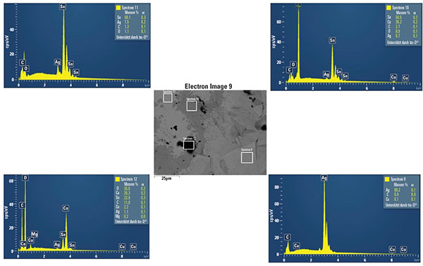
FIGURE 7. EDX analysis: The samples after reflow showed less contamination than before reflow.
Soldering Performance
Finally, the soldering performance was characterized within a flux-free reflow environment using vacuum and formic acid. To simulate a typical power module configuration, a Sn95/Sb5 alloy was selected for the solder preforms tested for both die-attach and substrate-attach interfaces. The tacking material was then applied in accordance with the optimal application parameters described earlier. FIGURE 8 summarizes the formic acid reflow profile used, including temperature, atmosphere, and time duration parameters.
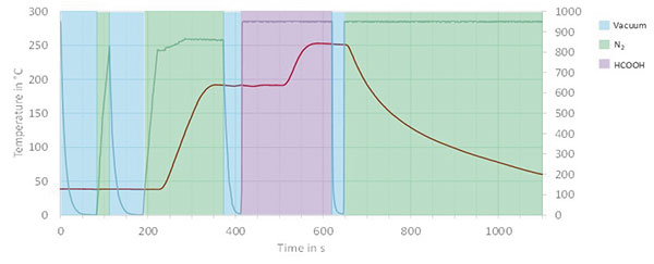
FIGURE 8. Soldering reflow profile.
The evaluation consisted of wetting and voiding analyses (FIGURE 9). The wetting test samples demonstrated good uniform coverage on the surface, and good edge definition consistent with high-quality soldering performance that is typical in flux-free power module processes. In concert with the positive wetting results, the voiding performance of approximately 1% over the solder interface area was comparable to typical production quality results for power module assemblies.
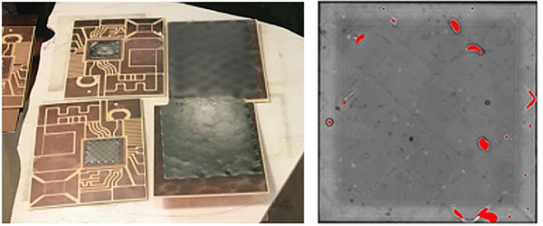
Figure 9. Soldering results showed good wetting (left) and voiding (right) of 1.0%.
Conclusions
The tests show the tool-free concept analyzed through this effort, featuring a novel no-residue tacking material, to be a viable alternative to fixturing and alignment jigs in power module manufacturing. Positive mechanical properties with tack strength and working time demonstrate the ability to maintain precise preform and assembly alignment during manufacturing. In addition, the absence of residue and temperature processing characteristics make this material a solution for no-flux reflow techniques used in power module manufacturing. Results indicate no impact to soldering performance or quality when this tacking material is used in lieu of fixturing. Finally, the reduction in fixturing design effort, material costs, process time, and complexity with the tool-free assembly concept make this a promising approach to reduce the overall cost of ownership for power module manufacturers and presents an opportunity to scale production more readily.
Outlook
Initial tests to leverage this tacking material for other applications such as pressure silver sintering are currently ongoing. The benefit of the tacking in this case is the avoidance of the hot-die placement, which is akin to another heating/drying step at the sintering processes. Results from this testing will be a focus of future work. •
References
1. P. Ning, H. Li, Y. Huang and Y. Kang, “Review of Power Module Automatic Layout Optimization Methods in Electric Vehicle Applications,” Chinese Journal of Electrical Engineering, vol. 6, no. 3, September 2020.
2. W. Lin and Y. Lee, “Study of Fluxless Soldering Using Formic Acid Vapor,” IEEE Transactions on Advanced Packaging, vol. 22, no. 4, November 1999.
3. R. Behera, “Development of Fluxless Reflow Soldering Process for Reliable Attachment of Dice for Space Applications,” International Journal of Pure and Applied Mathematics, vol. 118, no. 16, 2018.
4. A. Hutzler, C. Oetzel and E. Friker, “Improvement of Power Module System Solders by Directional Solidification,” 10th International Conference on Integrated Power Electronics Systems, (CIPS) 2018.
Acknowledgments
The authors would like to recognize several key contributors for this project: Stefan Strixner, Zestron; Olivier Matthieu and Nico Kuhn, Rogers Corp; David Hu Di, Evan Griffith, Dr. Hyoryoon Jo, Miloš Lazić, Karthik Vijayamadhavan, and Graham Wilson, Indium Corp.
is product manager for engineered solder materials, focusing on power electronics applications, at Indium Corp. (indium.com). Prior to joining Indium, he spent more than 10 years as an engineer and product manager in the electronics industry. He has a bachelor's in mechanical engineering and an MBA from Clarkson University and is a Certified SMT Process Engineer (CSMTPE); jhert-line@indium.com.
PCB West: The leading technical conference and exhibition for electronics engineers. Coming Oct. 4-7 to the Santa Clara (CA) Convention Center. pcbwest.com


Press Releases
- Altus Group Invests in Major Headquarters Expansion to Showcase Complete Turnkey Manufacturing Capability
- ViTrox Americas Welcomes Eric Cruz as Technical Support Engineer
- ECD Strengthens Engineering Team with New Software Development Hire
- ViTrox Americas Welcomes Doug Ennis as Senior Field Applications & Service Engineer