Design for Robotics Manufacturing
“DFRM” reveals potential manufacturing issues and the sample of processes that can feed those issues back for design review.
As detailed in Circuits Assembly last year (“Robotics Assembly from Prototype to Production,” March 2013), robotics has received an increase of attention in the media thanks to overall advances in the technology.1 This article details some of the key areas of design for robotics manufacturing (DFRM), and provides recommendations for products transitioning from the design to production phase.
During the prototype or design verification build stage, the main goal is to prove out the bill of materials (BoM), assembly drawings and overall robotics design. This is the phase when manufacturing issues are documented and fed back for resolution before a product is released to production.
The following are examples of areas of focus during the prototype review:
Form, fit and function. Two validations exist during the form, fit and function stage. First is a design review of the build documentation, including design models, BoM and assembly drawings. Depending on tools available, the review could be electronically automated or manual, with the result a validation that the overall build documentation meets the intended design intent. The second validation is the actual assembly of the robot and how all the material fits together. Problems may occur with sheet metal, plastic material or wire routing interference issues. Wire routing may require additional review, given the opportunity of pinching, wires unplugging or other reliability concerns. If any of these issues occur, an engineering change order (ECO) may be required to the design model and assembly drawings.
Rework or modification to material may be required to make the prototype “fit” together. As with any modification, an increased attention should be made on the impact to the next-level assembly. The important takeaway of this rework is to incorporate a permanent correction into the next assembly build or product roadmap. Issues may also occur during revision changes of a dimension modification. The goal is to verify the fit, modify if necessary and address and incorporate all changes before the follow-up build or before the introduction-to-production phase.
During the design and build review, consider analysis tools such as PFMEA (Process, Failure, Mode, Effects and Analysis) or equivalent to assess areas of the process in which error proofing (Poka yoke) tools or methods can be used. The PFMEA review can look at materials, methods, process and equipment. Similar analysis can be completed during the initial design stage (DFMEA - Design, Failure, Mode, Effects and Analysis). These reviews assess the areas at risk, categorize and prioritize the risk, and determine what can be implemented to prevent the issue from occurring. Typically, this exercise is completed with a cross-functional team to ensure a variety of backgrounds, experiences and knowledge, which ensures a comprehensive assessment is performed.
Ease of manufacturing. Following the DfM process after the form, fit, function review, ease of manufacturing is assessed. Ease of manufacturing identifies ways to reduce product cycle time and improper quality. These ideas range from the simple to the complex. Examples include using captive washer screws or pre-applied adhesive verses hand-applying adhesive. Another example is having multiple wires or cables harnessed together for ease of routing and assembly.
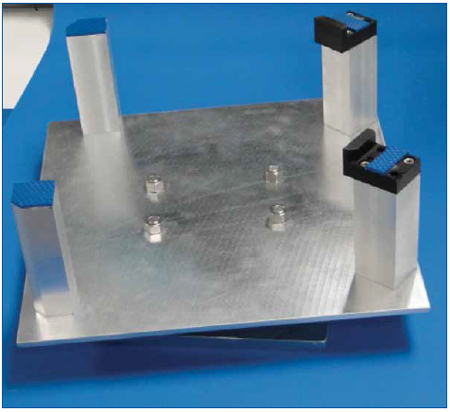
In addition to changes in material, correct selection of equipment and tooling can greatly help the ease of manufacturing. If an assembly has many screws at the same operation and torque setting, an electric or automated screw driver may assist. An assessment may be required to justify the expense or return on investment of the purchase. Custom designed fixturing may be the most helpful of all ease-of-manufacturing recommendations. These fixtures may assist with product support, various assembly operations (such as press-fit), material handling and inspection. Figure 1 shows an example of a custom fixture, designed and manufactured at Benchmark Electronics NH Division for a medical robotics program. Some of the benefits of this custom fixture include reduced process cycle time and increased product quality through better material handling.

Figure 1. Custom designed turntable fixture for ease of manufacturing. (Courtesy Benchmark Electronics NH Division)
Quality control and test review. As discussed above, the initial design build is an important DfM review tool to ensure form, fit and function of a robotics assembly. Two additional important inputs result from quality control and testing of the subassemblies and completed robotics assembly. These two inputs will also be fed back to the DfM review as potential design change for future builds.
During quality control or visual inspection, among the items reviewed include adherence to internal and external criteria, industry standards and potential areas of concern for functionality of the subassemblies. Cosmetics issues will also be reviewed for the completed robot, usually focusing on external surfaces visible to the end-customer.
Depending on the end-application, various noise levels such as fans, motors and gears may be an area of DfM feedback.
The acceptable noise level for a robot in an industrial or military application may be quite different from one in a medical or office environment.
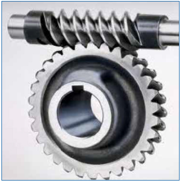
Figure 2 shows an example of a gear system. In cases of motors and gears, testing feedback through the subassembly and final robotics system test will impact DfM review. Testing will verify design, functionality and application with a complete load placed upon the assembly. Be aware of the noise and overall decibel level and consider the final customer application and environment.

Figure 2. Sample gear system. (Courtesy howstuffworks.com)
References
1. Scott Mazur, “Robotics Assembly from Prototype to Production,” Circuits Assembly, March 2013.
Scott Mazur is manufacturing staff engineer at Benchmark Electronics (bench.com); scott.mazur@bench.com.
Press Releases
- Altus Reports Growing Demand for Guidance on Convection Reflow Oven Specification
- Coherix Opens New Adhesive-Dispensing Vision Center in Europe
- Pan Pacific Strategic Electronics Symposium Program Finalized
- The Most Critical 2 Inches in SMT Manufacturing – When a Splice Fails, the Line Fails, Full Stop. Throughput and Yield Depend on One Overlooked Moment


