

The Use of Particle Impact Dampers (PID) to Prevent Damage from Vibration
Lab tests show the addition of COTS parts significantly improves time to failure.
Harsh vibration has been shown to cause premature component failure and damage to printed circuit board assemblies. Such vibration and consequent failures can be mitigated using a new series of Particle Impact Dampers (PID) developed originally by NASA to reduce random vibration in PCB assemblies in harsh environments. PID can be installed on new assemblies, or added to heritage hardware. PID extends hardware life. It is a lighter, simpler solution that reduces the need for redundant systems. After vibration hardening, old hardware is ready for new missions in new operating environments. Here, the authors examine some practical design considerations for PID with the goal of preventing random vibration failures in PCB assemblies.
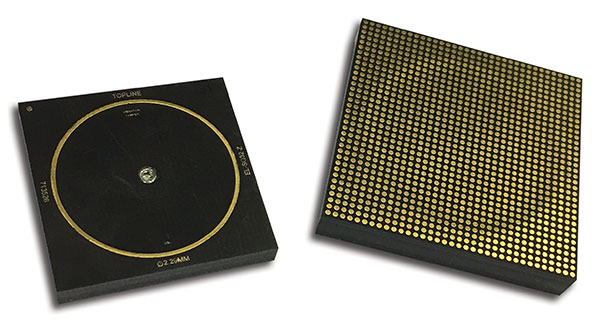
Figure 1. SMT solder mounting to PCB as with standard component. Alternative attachment by adhesive epoxy.
What is PID? The PID is a mechanical component that surface-mounts onto the PCB. Inside the PID is a payload of freely moving tungsten balls that move in the opposite direction to the board. This counter motion pulls back the bending of the board and attenuates vibrational energy. PID technology works at fundamental mode vibration frequencies, typically 100Hz to 2KHz. PID can operate over a full range of temperatures without derating.
The PID is housed in a sealed container that is filled to 90% with tungsten balls. The counterbalance impact of tungsten balls in the PID dampens fundamental frequency fo mode vibrations in the PCB assembly. This maximizes energy transfer to the PID to dampen vibration. The weight of the tungsten inside the PID is approximately 10% of the mass of the PCB assembly.
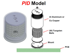
Figure 2. Exploded view of cylindrical PID system.
The PID is mounted near the geometric center of the PCB where vibratory forces are the greatest. The kinetic energy is transferred to the PID to dampen vibration in the circuit assembly. PID provides better reduction in vibration than alternative mitigation methods such as adding heavy metal supports, bumpers or increasing the thickness of the PCB.
PID technology works without batteries or electrical power. The motion of the tungsten balls in the sealed PID housing removes vibratory energy from non-linear vibroacoustic environments such as PCB card assemblies. Losses and damping occur during impacts between the tungsten balls and the walls. The PID straightens the PCB at the central lobe and attenuates vibration by pushing and pulling the PCB in the opposite direction after the tungsten balls overcome gravity. PID is also suitable for tuned beam fixtures.
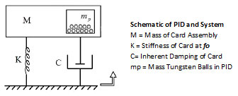
Figure 3. Mechanical schematic of PID closed-loop system.
Mounting and application. PIDs are commercially available off-the-shelf components (COTS). Mounting methods include standard surface-mount soldering, LGA or BGA, screw-mounting and epoxy-mounting with permanent epoxy adhesives.
Vibration is attenuated by mounting a PID near the geometric center (anti-node) of the PCB. The damping effect increases reliability in the PCB. The PID may be located on either side of the board. The PID may also be attached to an optional interposer bridge to avoid interference with existing components on the board.
Vibration at the fundamental frequency fo causes bending, fatigue and cracks in the PCB assembly. Excessive vibration from external excitations leads to catastrophic failure. NASA invented PID technology to reduce vibration and increase reliability in circuit board assemblies.
Tungsten (W) is environmentally friendly. Tungsten’s properties include high density and tensile strength. The PID can fully function at extreme temperatures without derating.
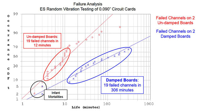
Figure 4. Failure analysis comparison of undamped and damped 0.090"-thick PCB assembly on NASA vibration table.
Invention and development. Ron Hunt of the NASA Marshall Space Flight Center is the inventor of PID technology for attenuating vibration in circuit boards. PID technology has been demonstrated to attenuate destructive vibratory forces and extend the life of the PCB assembly, including IC packages that operate under harsh environmental conditions, including thermal stress and vibration. The NASA invention US Patent (no. US9521753 B1) describes a “Vibration Damping Device for Circuit Card Assemblies.” TopLine has been granted an exclusive worldwide license by NASA to manufacture “Particle Damping for Vibration Mitigation for Circuit Cards.” NASA made a technology transfer of the patent to TopLine in September 2016.
Experimental
Weibull failure analysis #1. A destructive life test was performed at NASA’s Marshall Space Flight Center using 0.090" (2.3mm) thick, 4" x 7" (10 x 18cm) PCB assemblies. Four 21 x 21mm daisy-chain 400-I/O column grid array (CCGA) components were mounted on each board. One board was left undamped for baseline purposes. A PID was epoxy-mounted at the center of the second board. The boards were mounted side-by-side on a vibration table and subjected to excessive vibrations. Some 19 channels on the undamped boards (without PID) failed within 12 min. By comparison, 19 channels on the damped boards (with PID) survived 5 hr. (306 min.) before ultimately failing.
Weibull failure analysis #2. Comparison was made between assemblies of two different board thicknesses: 0.070" (1.78mm) versus 0.090" (2.3mm). The board size was 4" x 7" (10 x 18cm). A total of eight assemblies were tested, four of each thickness. Four 21 x 21mm daisy-chained 400-I/O CCGA components were mounted on each board. Two boards of each thickness were left undamped. A PID was epoxy-mounted at the center of the other boards. Boards of the same thickness were mounted side-by-side on a vibration table and subjected to excessive vibrations. A channel failure was defined as a total increase in resistance greater than 1000Ω connected through 100 I/O columns during vibration testing. The time for each failure was recorded. A Weibull analysis of channel failures for damped and undamped boards of two thicknesses was recorded. In all cases, damped assemblies with PID survived longer. The damped thinner boards (0.070") with PID survived longer than the undamped thicker board (0.090") without PID.
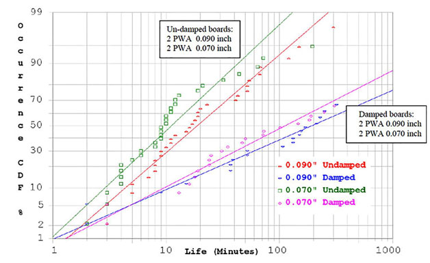
Figure 5. Failure analysis comparison of undamped and damped 0.070" and 0.090"-thick PCB assemblies on NASA vibration table.
Fretting too? TopLine is launching an alpha project and seeking input from customers and industry friends to investigate if PID technology can be adapted to attenuate (dampen) micro-vibrations that cause fretting.
The goal is to reduce fretting caused by micro-vibration between the mating of PCBs and their associated sockets (connectors). Repeated small rubbing of mechanical movements (fewer than 5 mils or 125µm) leads to product failure, as studied by the science of tribology. Over time, fretting corrosion results in electrical deterioration, data loss, thermal runaway and ultimately circuit failure. Such small movements can occur hundreds or thousands of times per second by mechanically induced vibrations from fans, relays, motors or reverberating sound. CTE mismatch of materials can also result in warpage and flexing of the circuit board, albeit at a slower rate. Contacts moving relative to one another can occur in all directions: vertical, radial, axial or transverse. Eventually the gold plating will wear thin, and the underlayer nickel will rub against copper fingers on the PCB.
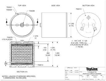
Figure 6. Outline drawing of tunable PID.
Conclusion
Mitigating the effects of random vibration through the use of PID has been demonstrated in laboratory studies to extend the life of PCB assemblies and components, thus giving electronic assemblies a longer and more reliable working life. PID is intended to be commercially available COTS components, and as such, enable this technology affordably within the reach of SMT PCB assemblers worldwide.
is president of TopLine Corp. (topline.tv); hart@topline.tv. is with the NASA Marshall Space Flight Center and inventor of PID (nasa.gov/centers/marshall).


Press Releases
- XLR8 EMS Welcomes Raul Jorge Lopez Jr. as Director of Program Management and Procurement
- Koh Young America Promotes Ramiro Mora to Lead Service and Applications in Mexico and South America
- ViTrox Americas Welcomes Huy Pham as Technical Support Engineer
- XLR8 EMS Appoints Steve Dutton as Chief Sales Officer