Jet-Printed Solder Paste and Cleaning Challenges
Are process settings for Type 3 and 4 pastes sufficient for Type 5 and 6 too?
A leading OEM has demonstrated that mixing current pastes with jet-printed paste can fully pass all qualification tests.1 In this way, jet printing can meet flexibility demands without loss of throughput.
One drawback to jet printing is that it requires jettable solder pastes. What does this imply? Understanding the makeup of solder paste is critical to understanding the requirements of jettable solder paste. Essentially, solder paste is a suspension of solder particles in a flux-containing vehicle, in which the shape and size of the particles and the flow properties or rheology of the flux vehicle are matched to the method of paste application most appropriate to the design of the SMT assembly.2 For typical solder pastes, the typical metal content is between 88 to 91% by weight, and about 30 to 70% by volume.3
Metal solder particles are spherical, as this helps to reduce surface oxidation and ensures good joint formation with adjoining particles. Solder powder particle size is classified by IPC in accordance with J-STD 005 (TABLE 1).4
Table 1. % of Sample by Weight: Nominal Size (µm)
For print applications, solder paste Types 3 and 4 are typically used. However, all jettable pastes are Type 5 and 6, with particles smaller than 30µm. As identified in Table 1, Types 5 and 6 solder pastes are made with solder spheres that are smaller in diameter. Thus, the resulting solder powder is finer. With miniaturization advancing quickly for advanced packaging, solder powder used in paste materials also needs to get finer. As noted, all solder pastes contain flux that facilitates flow behavior during the application process.
Printable pastes contain the lowest content of flux, which is attributed to the robustness of the printing process. On the other hand, higher flux content seems to be needed to reach a constant flow through channels of different sizes during dispensing and jetting.5 Thus, for jettable solder pastes the metal content can be reduced by about 10 wt.-%, meaning flux content is increased by 10 wt.-%. As a result, a greater amount of flux residue may be present on the substrate surface or underneath components following heat cycle(s). Therein lies the challenge for the electronic assembly cleaning processes.
Aqueous-based cleaning agents are commonly used to remove post-solder flux residues for all paste types: no-clean, rosin-based, synthetic or water-soluble based. Anecdotal evidence suggests an optimized aqueous-based cleaning process for a given paste type may not produce the same results for the same process if the equivalent jettable solder paste is used. Given the higher flux content of the jettable solder paste, this is not surprising. Thus, a design of experiment (DoE) was developed to assess the cleaning requirements of five jettable solder pastes employing an aqueous-based cleaning system with a variety of engineered cleaning agents, including pH neutral and alkaline-inhibited and uninhibited cleaning agents.
Methodology
The main purpose of this study was to evaluate the cleaning efficiency of the industry standard aqueous-based defluxing agents on populated surface mount PCBs that are assembled with jet printable solder pastes. The visual inspection was carried out in accordance with current IPC standards for cleanliness assessment. For this study, only surface and under- component inspection was evaluated. Other quantitative cleanliness assessment techniques were not included in this study, since the study’s purpose was to strictly assess the efficacy of various cleaning agents on jettable solder pastes.
As under-component cleanliness assessment was the focus of the study, a test vehicle was selected and assembled with commonly used surface mount components using jet printable pastes at an equipment supplier having jet printing capability. The assembled boards were subsequently subjected to cleaning trials.
For the cleaning process, spray-in-air conveyorized inline and batch cleaners were used with seven leading aqueous-based cleaning agent alternatives. Following cleaning, the boards were visually inspected for surface contamination. Additionally, all components were mechanically removed for visual inspection for under-component cleanliness.
Main Research
TABLE 2 lists the five commonly used jettable solder pastes selected. The test vehicle (FIGURE 1) used for all cleaning trials was populated with several common low-standoff surface-mount components. In total, 70 boards were populated (35 each for both batch and inline trials). Thus, two boards were prepared for each paste type, and each board was populated with a total of 86 components (TABLE 3). Leaded and lead-free reflow profiles were used, as required per TABLES 4 and 5.
Table 2. Solder Paste Selection
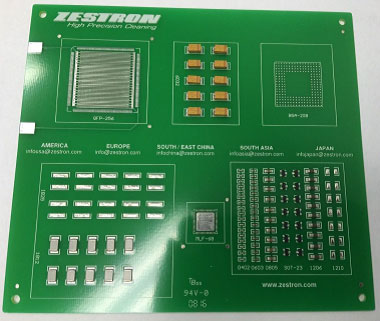
Figure 1. Test vehicle.
Table 3. Component Types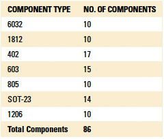
Table 4. Leaded Profile, Belt speed: 45 in./min
Table 5. Lead-Free Profile: Belt speed: 75 in./min
Component standoff heights were measured to assess consistency of component placement (TABLE 6).
Table 6. Component Standoff Heights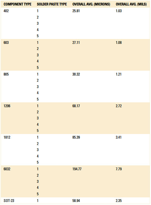
FIGURES 2 and 3 are representative pictures of the leaded and lead-free component standoff height.
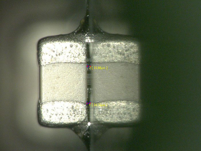
Figure 2. Paste A, leaded (0402) component standoff height.
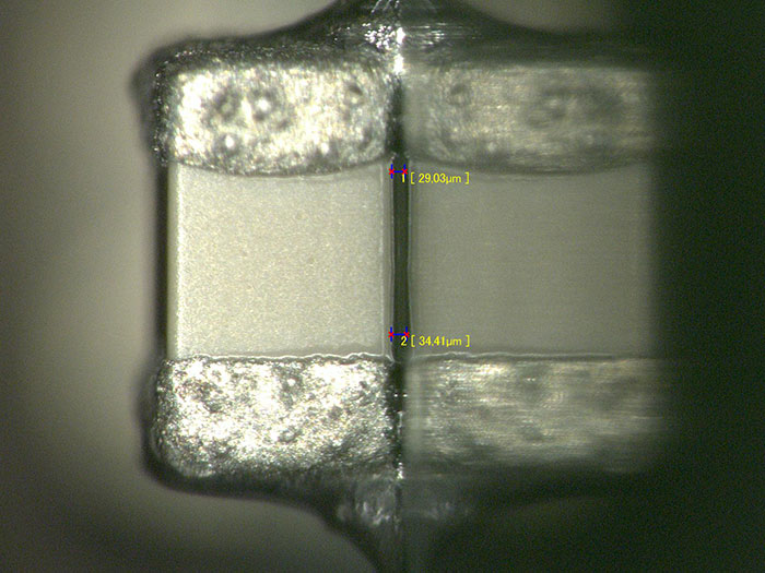
Figure 3. Paste B, lead-free (0402) component standoff height.
The inline cleaner was configured with a standard intermix spray bar configuration. For both the inline and batch cleaning trials, a 10% cleaning agent concentration was selected, with a wash time of 5.2 min. (1 ft./min. inline conveyor belt speed) and 10 minutes for the inline and batch cleaner, respectively. All cleaner operating parameters were maintained constant for all trials per TABLES 7 and 8. Test parameters were designed to compare cleaning results and not to achieve 100% cleanliness with each cleaning agent.
Table 7. Inline Cleaning Parameters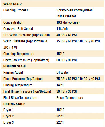
Table 8. Batch Cleaning Parameters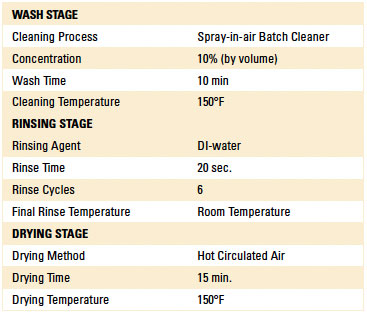
Cleanliness assessment by visual inspection was conducted on the board surface and under the component. Visual inspection was performed in accordance with IPC-A-610A utilizing a microscope at 40x viewed vertically at a slanted angle. A polarized filter was used to improve contrast during inspection. Each board was inspected by three different application engineers, independent of each other, and results were averaged for each board.
For the under-component cleanliness evaluation, all components were sheared from the boards, and the visual inspection rating criteria were reported as either fully cleaned or not cleaned. Evaluations from the three engineers were recorded and, for each board, were averaged and reported for each cleaning agent and solder paste type.
The percent under-component cleanliness per board calculation is as follows:
Avg. under-component cleanliness = No. of components fully cleaned
Total no. of components
Table 9. Cleaning Agent Types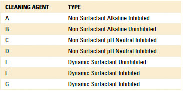
Inline and batch process discussion. Results for under-component cleaning with the inline cleaner are shown in TABLES 10 and 11 and FIGURES 4 to 6. Results for under-component cleaning with the batch cleaner are shown in TABLES 12 and 13 and FIGURES 7 to 9.
Table 10. Inline Cleaner, Overall Under Component Cleanliness Results for All Cleaning Agents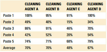
Table 11. Inline Cleaner, Overall Cleanliness Under Component Results by Component Type
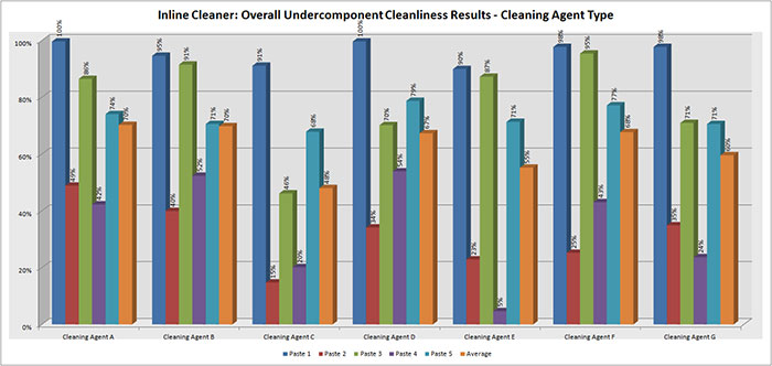
Figure 4. Inline cleaner, overall cleanliness under-component results by cleaning agent type.
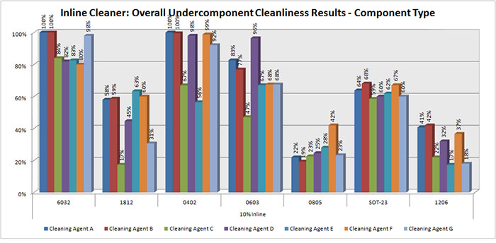
Figure 5. Inline cleaner, overall under-component cleanliness results by component type.
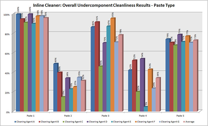
Figure 6. Inline cleaner, overall under-component cleanliness results by paste type.
Table 12. Batch Cleaner, Overall Under Component Cleanliness Results for All Cleaning Agents
Table 13. Batch Cleaner, Overall Under Component Cleanliness Results by Component Type
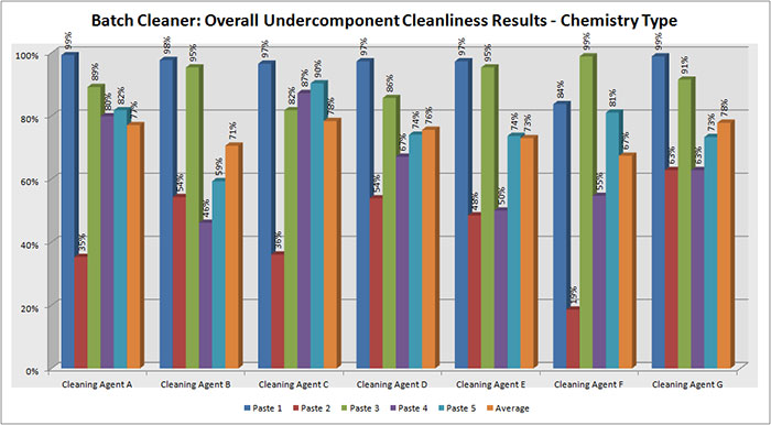
Figure 7. Batch cleaner, overall under-component cleanliness results by cleaning agent type.
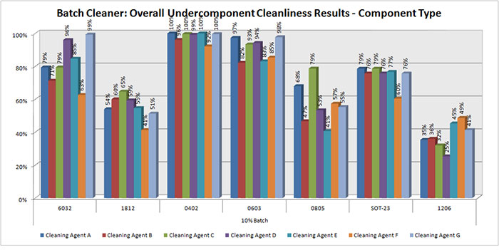
Figure 8. Batch cleaner, overall under-component cleanliness results by component type.
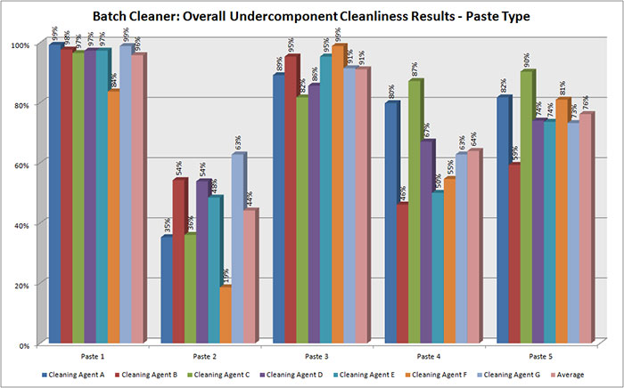
Figure 9. Batch cleaner, overall under-component cleanliness results by paste type.
The inline cleaning process results regarding under-component cleanliness were varied. All cleaning agents produced excellent results with Paste 1 (96% overall). Paste 2 and 4 proved most difficult to clean, with overall results averaging 32% and 34%, respectively (Table 10).
The batch cleaning process also produced varying results regarding under-component cleanliness. Pastes 1 and 3 averaged the highest cleanliness assessment result, while Paste 2, 4 and 5 proved most difficult to clean, averaging 44%, 64% and 76% cleanliness levels, respectively (Table 12).
It should be noted the cleaning process was not optimized for the paste type or cleaning agent used, as this study was to assess the relative differences of cleaning each paste with various cleaning agent types under same process conditions. This study provided insight as to the type of cleaning agent that may be best-suited for cleaning a particular jet-printed solder paste and to understand challenges associated with cleaning post-solder flux residue from jet-printed solder paste and apply lessons learned to field applications.
Case Study A – Aerospace OEM
An aerospace OEM was experiencing cleaning challenges with boards assembled using Paste 3. The OEM was using an aqueous-based cleaning agent in a batch cleaner with limited success, as cleaning under low-standoff components was problematic. Acceptable results were only achievable at 180°F wash temperature and one-hour wash cycle time. At this temperature, cleaning agent evaporation loss and ink marking removal were the main concerns. The OEM was seeking an alternate solution, enabling use of the cleaning agent at lower temperatures to maximize cleaning process efficiency, prevent label ink marking removal and minimize process costs. Given the information obtained through the initial jet paste study, the authors chose cleaning agent F as most suitable for the OEM’s cleaning process.
Given the sensitive nature of its products, the OEM was unable to provide actual substrates for the initial cleaning evaluation. Thus, the authors used an industry test vehicle for all cleaning trials.
Methodology. Eleven test vehicles were prepared for this evaluation. In this case, the OEM fully populated the test vehicles at its facility and sent them out for cleaning trials. Note the standoff height on the boards populated by the OEM was substantially lower than those on the test vehicles used for the internal study (TABLE 14). The eleven test vehicles were fully populated with 106 components on each board per TABLE 15 and FIGURE 10.
Table 14. Test Vehicles Standoff Height (mils)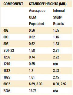
Table 15. Component Types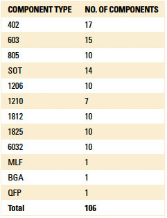
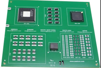
Figure 10. Aerospace OEM populated test vehicle.
Representative images of component standoff heights are detailed in FIGURES 11 (0402) and 12 (0603). In collaboration with the aerospace OEM, it was decided that under-component visual inspection would be used for cleanliness assessment for this evaluation. Visual inspection was conducted in accordance with IPC A-610F, vertically viewed.
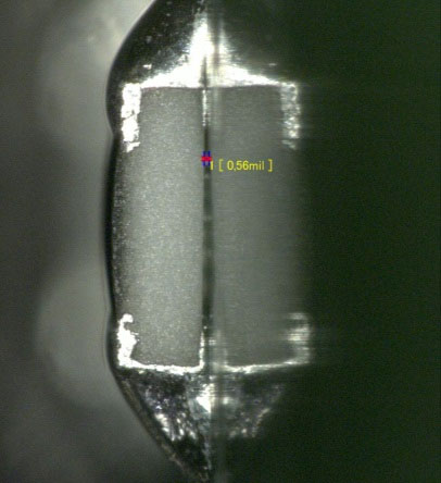
Figure 11. OEM populated, 0.56 mils standoff height, 0402 component.
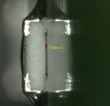
Figure 12. OEM populated, 0.62 mils standoff height, 0603 component.
For the batch cleaner, the operating parameters selected are detailed in TABLE 16. Two sets of trials were conducted employing cleaning agent concentrations of 15% and 20%. All other batch cleaner parameters were maintained constant.
Table 16. Cleaning Parameters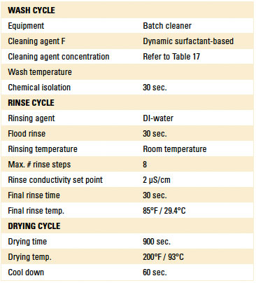
The cleaning process effectiveness was evaluated through under-component cleanliness assessment. For all trials conducted, components were sheared from the test vehicle, and the under-component surface was inspected and defined as either fully clean, or not clean. The number of clean components was expressed as a percent of the total number of components on the test vehicle, with results shown in TABLE 17.
Table 17. Case Study Results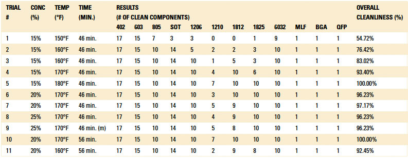
Based on the results in Table 17, components 1210, 1812 and 1825 were found most difficult to clean. Recognizing this, it was decided to combine the cleanliness results of these three component types from trials 3 to 6 and 10 and 11 in order to assess the effectiveness of the cleaning trials indicated in TABLE 18. Based on the above findings, wash temperature and wash time were found to be the main parameters affecting cleanliness results (FIGURE 13). Wash temperature seems to have the most impact on the cleaning results, followed by wash time and concentration.
Table 18. Under-Component Cleanliness Assessment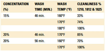
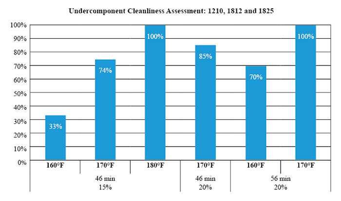
Figure 13. Cleanliness under 1210, 1812 and 1825 components.
Representative pictures of under-component cleaning are shown in FIGURE 14.
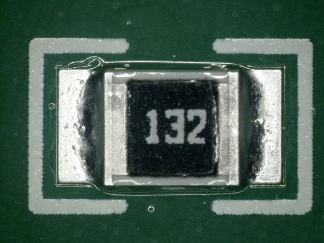
Figure 14A. Component 1210 before cleaning.
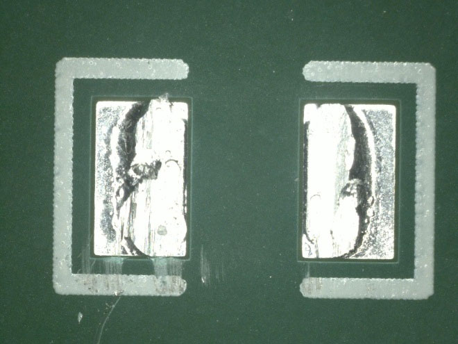
Figure 14B. Component 1210 after cleaning.
Conclusions. Excellent results were achieved in the cleaning trials conducted on the boards received from the aerospace OEM, as cleaning agent F was able to fully clean the jet-printed post-solder paste residues on the surface and under the component. It was observed that 100% cleaning results were obtained under TABLE 19 conditions.
Table 19. Optimal Cleaning Parameters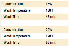
For this cleaning process, wash temperature does have the most significant impact on cleaning results, followed by wash time and then concentration of cleaning agent. It should also be noted that component standoff heights of various components on the industry test board soldered by the aerospace OEM were significantly lower compared with the same test boards and components soldered for the internal study, thus increasing the cleaning challenges.
Case Study B – EMS
A leading contract manufacturer with design and assembly services decided to employ jet printing using a lead-free no-clean solder paste (Paste 2). Given the production and reliability standards required, it specified using an aqueous-based inline cleaning process. It requested assistance for the qualification process, including cleaning agent recommendation and cleaning process operating parameters. Also, as its assemblies included sensitive materials, material compatibility with the cleaning process was critical. Additionally, the CM requested cleaning compatibility assessment with selected labels used on its substrates.
Methodology. A DoE was developed, and a pH neutral cleaning agent was specified (cleaning agent C), as defined in the original study, and a CM-selected inline cleaner was used for all trials. The CM provided eight double-sided substrates for use in the cleaning trials. Side A was reflowed twice, while side B was reflowed once. Due to confidentiality restrictions, pictures of the substrate cannot be included. However, pictures of the heatsinks, as well as the test substrate used for label compatibility, are available (FIGURES 15 to 17).
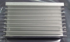
Figure 15. Side A of the anodized aluminum heatsink.
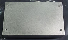
Figure 16. Side B of the anodized aluminum heatsink.
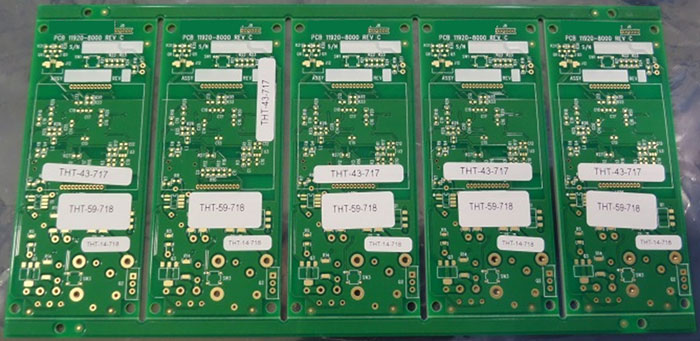
Figure 17. Label compatibility, without reflow.
All substrates were reflowed at the CM site and sent out for the cleaning trials. As the CM was interested in assessing the impact of staging time between reflow and cleaning, substrates were reflowed 24 and 72 hrs. prior to cleaning. Additionally, label compatibility was analyzed on substrates without reflow, as well as substrates with lead-free reflow. Two cleaning agent concentrations and conveyor belt speeds were selected for the inline cleaning trials.
Per the CM request, cleanliness assessment methodologies included visual inspection (substrate surface only) in accordance with IPC-A-610F and ionic contamination analysis per IPC-TM 650 and J-STD 001F. The substrates used for the label compatibility analyses, as well as the anodized aluminum heat sink, were evaluated with the cleaning process separately. All inline cleaner operating parameters are detailed in TABLE 20.
Table 20. Inline Cleaner Operating Parameters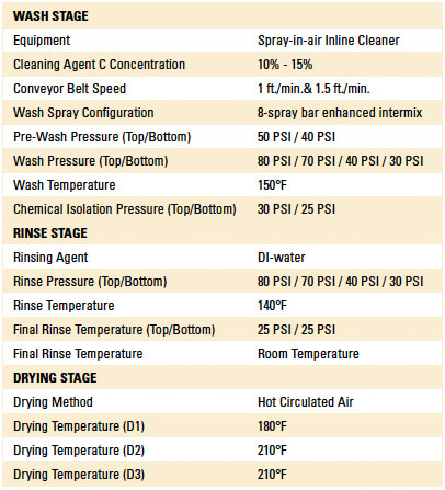
Results. FIGURES 18A to 20B show the critical areas on the substrate before and after cleaning. Visual inspection results are detailed in TABLES 21 and 22.
Ionic contamination testing was conducted per IPC-TM-650. Standards were based on J-STD-001F. The pass/fail limit for this test is 10.06µg/in2. The substrate surface area is 49.5 in2, with results shown in TABLES 23 and 24.
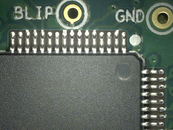
Figure 18A. Trial 1 before cleaning.
Figure 18B. Trial 1 after cleaning.
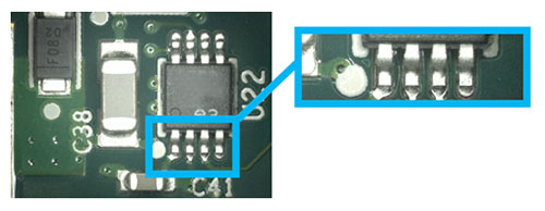
Figure 19A. Trial 2 before cleaning.
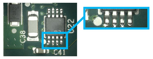
Figure 19B. Trial 2 after cleaning.
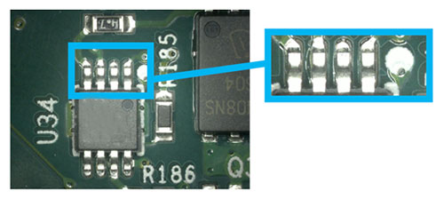
Figure 20A. Trial 10 before cleaning.
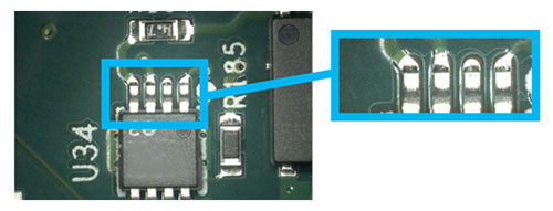
Figure 20B. Trial 10 after cleaning.
Table 21. Visual Inspection - 24 Hr. Time Interval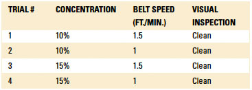
Table 22. Visual Inspection - 72 Hr. Time Interval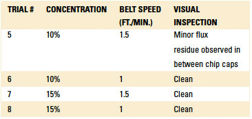
Table 23. Ionic Contamination - 24 Hr. Time Interval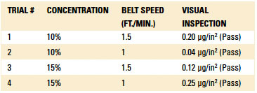
Table 24. Ionic Contamination - 72 Hr. Time Interval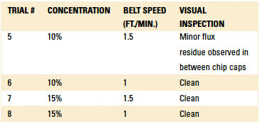
The anodized aluminum heatsink was passed through the inline cleaner three times using the most aggressive wash settings to simulate the worst-case scenario. Parts were inspected after each pass and found to be fully compatible with the cleaning process.
The CM provided three types of printed labels for testing. These labels were applied on test boards provided by the CM. One set of boards were reflowed using the lead-free profile. The boards were passed through the cleaning process at 15% concentration, 150°F wash temperature and 1 ft./min. belt speed. The labels were found to be fully compatible with the cleaning process.
Conclusions. Boards received from the CM were cleaned with excellent results, as the flux residues were completely removed. Boards were visually inspected to check for surface cleanliness. All board surfaces were found to be clean, except Trial 5 (cleaned at 10% concentration and 1.5 ft./min. belt speed, with time interval between reflow and wash of 72 hr.). However, all the cleaned boards passed ionic contamination testing, as the ion species was below the pass/fail limit. Anodized aluminum heatsinks and reflowed labels were found fully compatible with cleaning agent C and the wash processes.
Thus, it was confirmed post-reflow flux residues of jet dispensing lead-free no-clean solder paste (Paste 2) can be fully removed using cleaning agent C in a spray-in-air inline cleaner.
Overall Conclusions
This study confirmed matching the cleaning agent to the solder paste is critical. This preliminary data proved valuable in assisting the companies to provide an optimized cleaning process to both the OEM and the CM in the case studies discussed.
References
1. Nico Coenen, “Jetting Solder Paste Opens Up New Possibilities in your SMT Production,” SMTA International Conference on Soldering & Reliability, May 2013.
2. Solder Paste Basics, IDC Online, idc-online.com/technical_references/pdfs/mechanical_engineering/Solder_Paste_Basics.pdf
3. Michal Kravčík and Igor Vehec, “Study of the Rheological Behaviors of Solder Pastes,” 10th Scientific Conference of Young Researchers, 2010.
4. M. Koch, et al, “Precision Jetting of Solder Paste – A Versatile Tool for Small Volume Production,” IMAPS, October 2014.
Acknowledgements
The authors would like to acknowledge Mycronic and Practical Components for support in the work discussed in this paper. This article was originally published at IPC Apex Expo in February 2018 and is republished here with permission of the authors.
is senior application engineer, is application engineer and is application technology manager at Zestron Americas (zestronusa.com); ravi.parthasarathy@zestronusa.com.
Press Releases
- Smartsol and Koh Young Technology Announce Strategic Partnership for the Mexican Market
- RBB Systems Boosts Manufacturing Capabilities with Equipment Upgrades for 2026
- 11th Class of Engineering Interns Begins Forging Success at Hyrel
- Rocka Solutions Announces 2026 Rockin’ Roundtable: An Interactive Discussion on What Really Drives SMT Printing Performance


