

Practical Thermal Profile Expectations in a Dual-Lane, Dual-Speed Reflow Oven
Developing a recipe that will satisfy both boards.
Dual-lane reflow ovens have been available for years, permitting two boards to be run at the same time in parallel. Until recently, circuit board manufacturers have been limited to processing the same boards or boards with like mass in each of the lanes, but dual-lane reflow ovens with independent lane speeds now make it possible to run boards with larger differences.
Now we have the ability to run different speeds in each lane; it is the process engineer’s responsibility to develop the recipe that will satisfy both boards. The following gives practical insight into a method to obtain this recipe.
To begin, understand factors that affect the transfer of thermal energy from the heater in a convection oven to the board. In most cases reflow oven fans push gas (air or nitrogen) across a heated electric coil to increase its temperature. Then the hot gas is distributed to the product through a series of holes in an orifice plate, as shown below. The equation that describes the transfer of energy from the hot gas to the board is well known
q = a · t · A · ∆T Eq. 1
where
q = the thermal energy being transferred to the board
a = the heat transfer coefficient of the board and components
t = time the board is in the heat
A = the surface area the heat sees
∆T = the temperature difference between the gas (convection) and the board
When we move the board parameters to one side of the equation and the oven parameters to the other side, we get
q = t · ∆T Eq. 2
a · A
By introducing a heavier or lighter board to the equation, the a and A factors change. Thermal energy absorbed by the board (q) then adjusts so the equation remains balanced. This change in thermal energy (q) results in a different board temperature. To maintain the board temperature, we must change either the zone set points (∆T) or belt speed (t).
Application. When running a new board in a single-lane oven, we adjust the profile by modifying the set points (∆T) and/or the belt speed (t) to obtain the correct profile. But if two different boards are run in a dual-lane oven, we can only change the belt speed because both lanes see the same temperature (set points).
In August 2009, a report published by BTU1 showed how changing the belt speed, zone set points and convection rate affected a solder reflow profile. It looked at how the furnace settings affected the peak temperature, time above liquidus and uniformity of two SMT boards. This new study varied the belt speed from 30 IPM to 60 IPM on a 75 gm, 360 g and 520 g board with eutectic and Pb-free recipes on a Pyramax 150 12-zone nitrogen reflow oven. The change in peak temperature, time above liquidus and soak time of each combination was recorded.
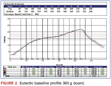
Eutectic recipe. The first step in the trial was to establish a baseline recipe that produced a standard ramp-soak-spike profile with the 360 g board at 45 IPM (Figure 2). The peak temperature was targeted at 220°C, time above liquidus (TAL) at 60 sec., and the time between 140° and 170°C at 70 sec.
Next the belt speed was changed in steps of approximately 5 IPM to a maximum and minimum of 15 IPM from the starting point on the three boards. We recorded the new peak temperature, TAL and soak time for each step. The results are shown in Figures 3-5.
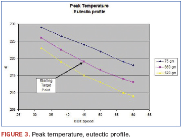
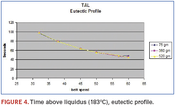
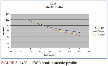
As expected, the board weights had an influence on the peak temperature with the heavier board being 7° to 10°C colder than the light board. But there was little difference in TAL or soak time between the boards.
The belt speed change affected all three parameters. The TAL and soak time were changed by almost 50 sec., and the peak temperatures varied by around 15°C.
Practical application. We then applied the data to the real-life situation of running two different boards in the same oven. We started with the 360 g board in one lane and wanted to run the 75 g board in the other. Figure 3 revealed we needed to increase the belt speed to 58 IPM (see Figure 6) to maintain the same peak temperature on both boards. Meanwhile, Figures 4 and 5 told us that the TAL and soak of the 75 g board would shorten to approximately 45 and 55 sec. with the 58 IPM belt speed.
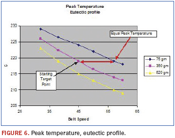
Likewise, if we wanted to run the 520 g board with the 360 g board zone temperatures, we needed a belt speed of 38 IPM to maintain the peak temperature. The resulting TAL would be 80 sec. and soak would be 85 sec.
If we could accept the new TAL and soak times, the new second board belt speed would work. If we could not accept the new TAL or soak, we would need to accept a different peak temperature on the new board or try different set points on both boards.
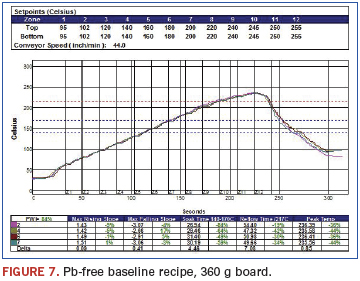
Pb-free recipe. Next we repeated the data acquisition for a Pb-free profile. We established the baseline recipe for a Pb-free ramp-to-peak profile on the 360 g board at 44 IPM (Figure 7). The peak temperature target was 240°C, with a time above the 217°C liquidus of 60 sec. Since there is usually little or no soak on Pb-free profiles, we monitored the time between 140° and 170°C in the event the soak becomes a consideration in the future.
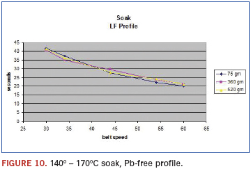
We then followed the procedure used with the eutectic profile and varied the belt speed ±15 IPM from the starting point. The new peak temperature, TAL and soak time were recorded for the various belt speeds with each of the three test boards. The results are shown in Figures 8, 9 and 10.
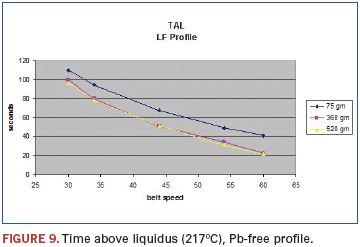
The board weights had the same effect on the peak temperature that we had with the eutectic solder profile. At the lower belt speeds, the difference between boards was about 7°C, and at the faster speeds, it was close to 13°C. But unlike the eutectic profile, where the mass did not affect the TAL or soak time, the TAL was about 20 sec. longer with the lighter 75 g board. (This most likely was due to the ramp to peak profile shape.)
When the belt speed was varied, all three parameters changed as in the eutectic profile. The TAL changed by 80 sec.; the soak time changed by 20 sec., and the peak temperature changed by around 15°C.
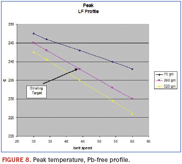
The charts gave us the same information as with the eutectic profile. The peak temperature chart (Figure 8) tells us that if we were using the recipe we established for the 360 g board, and we wanted to run a 75 g board in the parallel lane, we would need to increase the belt speed to 60 IPM. Figures 9 and 10 tell us that the TAL and soak of the 75 g board with a belt speed of 60 IPM would be approximately 40 and 20 sec.
Likewise, we could run the 520 g board with the 360 g board recipe at 39 IPM to maintain the peak temperature. The resulting TAL would be 62 sec. and soak would be 32 sec. If we could accept the change in TAL and soak, changing the speed would work in these cases.
Predictive software. After numerous profiles, it was realized that a method was needed to shorten the time it took to obtain the data for these charts. The data in the first trials were close to linear over the speed range; therefore, our first thought was to obtain the base profile on the primary board and then run two profiles on the secondary board with the same zone set points and belt speeds of ±15 IPM. We could then connect the dots, draw a parallel line, and come up with a new belt speed for the secondary board. This would require only three profiles to establish the preliminary belt speed estimate.
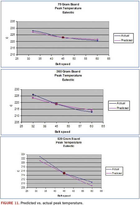
Next we wondered if predictive software such as KIC Navigator could be used to forecast the profile. We had used a KIC Explorer to obtain the original profiles for the trial, so it was an easy step to see what the KIC Navigator would predict if told to change just the belt speed on the Pb-free baseline runs for each board. The software predicted peak temperatures that were within 2° to 3°C of what was actually measured. The peak temperature predicted results vs. actual for the three boards, shown in Figure 11.
Conclusion
With a little understanding and work, a process engineer can develop the data to help find a recipe that will allow them to establish the set points and belt speeds for dual-lane dual-speed reflow ovens. It can be done in multiple runs with actual belt speed changes or as few as two runs by using predictive software. It will also help determine the extreme cases where the boards are too different to be run on a dual-lane dual-speed oven. In all cases, the engineer needs to confirm the results by profiling the actual boards at the belt speeds they determined would be best.
The great lesson is that after the first profiles are optimized on the reflow oven, much of the remainder of the work can be done at the engineer’s desk without tying up the production equipment.
A Common Recipe
Obtaining the baseline recipe for the primary board is an important step in the process of developing recipes for dual-lane dual-speed reflow ovens. In some cases ptimizing the set points for the peak temperature, TAL and soak time for the primary board could result in profile parameters that are unacceptable for the second board. When this happens, the process engineer needs to identify a different primary board recipe and try again. We asked ourselves if there was a way to combine the profile data from the two boards to find a common recipe that would allow us to make a midpoint tradeoff of the TAL, soak and peak temperature for both boards.
A discussion with KIC revealed an applications note describing a method of developing a common recipe for mixed boards that required only a belt speed change on a single process line to save changeover time.2 The note describes running two boards in the oven at the same time with TCs on both products. The software then suggests a common recipe that minimizes the PWI on both boards. It can even utilize different profile requirements for each TC or, in this case, board.
Applying the technique of running two boards at the same time to obtain a baseline recipe for the dual-lane dual-speed oven seems to have benefits for the first step. Although both boards might not be in specification, the error would be divided between the two boards, and belt speed changes could be done on each lane. The only problem would be to run two boards through the oven at the same time and not have the TCs tangle in the edge rail hangers, but this can be overcome by running the boards, one behind the other in one lane, with the appropriate board supports.
References
1. Fred Dimock, “Oven Adjustment Effects on a Solder Reflow Profile,” CIRCUITS ASSEMBLY, August 2009.
2. KIC application notes, Developing Common Reflow Oven Recipes for Mixed Production Lines Using the KIC Navigator, kicthermal.com.
Fred Dimock is manager, process technology at BTU International (btu.com); fdimock@btu.com.


