

Re-tinning New Components for High-Rel Assembly

Electroplated tin leads are not desirable because of the risk of whiskering.
There are a number of reasons to re-tin components from the stockroom prior to attaching them to an assembly. One example is the following: When building a high-reliability assembly using traditional Sn63 solder, one of the components is only available in a RoHS-compatible finish: in this case, electroplated tin. What to do? If the component is plated with tin, shouldn’t it be compatible with SnPb solder?
Well, not exactly. The added volume of tin in the plating, however slight, will change the percentage of tin in the solder joint, creating a new alloy that may have undesirable characteristics, such as being more brittle. The other reason for hot solder re-tinning is to prevent formation of tin whiskers, which tend to grow out of a plated finish, but won’t grow out of a fused alloy finish applied through dipping in hot solder. One cannot simply solder a component with Sn-plated leads to a circuit intended for military use, because any portion of that lead surface not wetted with solder has potential for tin whisker growth and catastrophic failure through shorting.
Therefore, what one has to do is remove that pure tin plating and replace it with a fused finish of the same solder alloy that is going to be in the connecting solder joint. This is the typical method of converting modern components born after RoHS with Pb-free finishes compatible with SnPb assembly, usually found in high-reliability or military applications. (Since RoHS, fewer components are available with SnPb finishes.)
If not plated with pure tin, these components may also have a gold plating finish on the leads that must be removed. Gold in the solder joint can lead to a phenomenon known as gold embrittlement. In the tinning process, these components, whether tin- or gold-plated, are dipped in a pool of solder to wash away the undesired plating. The components are then re-tinned with a SnPb finish.
The tinning process basically involves the use of two solder pots, the first one being the “sacrificial” pot that removes the unwanted plating of gold, tin, or other alloy. The second pot is the “virgin” pot that contains the alloy to be applied to the component prior to assembly. Essentially, the component is picked up, dipped in flux, then dipped in the first pot to remove the unwanted plating. During this initial dipping, the tinning system should employ some manner of agitation in the pot to produce a scrubbing effect for complete removal of the unwanted metallization.
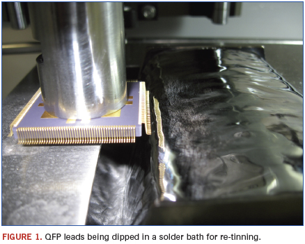
The component is then fluxed again and dipped into the virgin pot to apply the new fused finish. The component isn’t dipped flat, but is tilted, so that one side is dipped at a time. This is done primarily to prevent icicling, for a clean peel away of the solder. Inerting is also used to minimize icicling, particularly when using Pb-free alloys. Using an automated process ensures repeatability and consistency of results, and reduces the chance of operator-induced damage to fine-pitch leads. Dipping times for plating removal and re-tinning average about 2 sec. for each row of leads. Also, flux is applied through a dipping process to ensure uniform application and thorough fluxing for proper wetting.
Thus, the process, from removal of the component from the tray, through fluxing, preheating, dipping, visual inspection, followed by post-cleaning and washing, drying, inspecting, and return to the carrier, should be completely automated. Visual inspection mid-process ensures the absence of bridging, a real potential problem when tinning fine-pitch components such as QFPs. This is why the tinning process requires preheating, at a controlled temperature ramp to a desired set-point, especially important with ceramic components, prior to both the removal dip and the re-tinning dip. Preheating also minimizes potential for thermal shock or damage at the lead/body interface.
Depending on the material being removed, contamination levels in the sacrificial pot must be monitored, and it must be exchanged for a fresh pot when the level of gold or unwanted metal reaches saturation.
Alan Cable is president of A.C.E. Production Technologies (ace-protech.com); acable@ace-protech.com.


