

Choosing the Right Selective Soldering Type
A step-by-step matching of process to product type.
Automated selective soldering is a viable approach to enhance the affordability of certain electronics manufacturing operations. This step-by-step approach to selective soldering is meant to help decide which method is best.
Step 1: Decide if automated selective soldering can improve affordability in your product. Does the circuit card assembly mix surface mount technology and plated through-hole? A “yes” is imperative for selective soldering to be economically viable. Most cases of selective soldering are instituted to accommodate a small number of plated through-hole components usually manually soldered in an otherwise predominantly surface mounted assembly. These components are typically electrical connectors or high-power supply components available only in PTH versions.
Manual soldering is the obvious alternative and is typically used for prototyping a new assembly with a few PTH components. Because there is an inherent inspection operation in any manual soldering application (by the operator doing the soldering), an automated selective soldering operation requires a planned inspection step to maintain acceptable joints.
At this juncture, also ask, Is the product high- or medium-volume or is the product high-mix/low-volume? The answer will indicate the appropriate hardware and software combination to secure the most cost-effective automated selective soldering operation.
Step 2: Decide which type of selective soldering will be most effective:
- Selective aperture pallet (masked) wave.
- Mini solder wave with mask.
- Programmed solder fountain.
- Programmed laser.
Selective aperture pallet (masked) over wave solder. This is the simplest form of selective soldering, but must be balanced between the need to do selective soldering and production wave soldering. The selective aperture fixture effectively masks the areas previously soldered in the SMT reflow and non-selective wave soldering process, while exposing only those areas to be selectively soldered. The fixtured PCB assembly is then passed over traditional wave soldering equipment to complete the process. While each fixture is specific for a PCB assembly, wave soldering is a routine operation that is very cost-effective for small-volume/high-mix assembly.
Mini solder wave with mask. For higher volumes of product requiring selective soldering, the investment in smaller, dedicated wave solder equipment is economically justified by increasing production wave solder equipment availability.
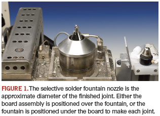
Programmed selective solder fountain. This process is slower than the two previous methods, but much more accurate in terms of solder volume and joint quality. A small fountain of molten solder (Figure 1) is pumped to each through-hole joint of the PCB. The PCB may be fixed and the solder fountain moved underneath the PCB using a precision, three-axis programmable gantry, or the PCB may be positioned over a stationary solder fountain. CAD-based board layouts can be imported to accurately position the board and solder fountain. Since each solder joint can be individually created, no unique fixturing is required. This technique requires both dedicated hardware and software and can be justified for extremely low-volume/high-mix applications.
Laser selective soldering system. Instead of a solder fountain, the laser selective solder system uses CAD data to position a laser (with solder wire feed) and directly solder any point on the board. The major advantage is the elimination of thermal stress to the surrounding board area. This noncontact soldering process produces consistent high-quality solder joints at typically one per second with maximum flexibility. It may even be possible to eliminate stencils and solder masks from the board to reduce manufacturing costs. This represents the most costly, but most productive method of selective soldering for very high-mix, very high-volume manufacturing.
Step 3: Select flux application method. Regardless of selective soldering equipment, there are two types of selective flux applicators: spray fluxer and dropjet fluxer. The spray fluxer applies atomized flux spray to a specific area, while the dropjet fluxer has more precise control over flux volume and PCB position. The final choice depends on the circumstances surrounding the soldering application.
ACI Technologies Inc. (aciusa.org) is the National Center of Excellence in Electronics Manufacturing, specializing in manufacturing services, IPC standards and manufacturing training, failure analysis and other analytical services. This column appears monthly.


Press Releases
- XLR8 EMS Welcomes Raul Jorge Lopez Jr. as Director of Program Management and Procurement
- Koh Young America Promotes Ramiro Mora to Lead Service and Applications in Mexico and South America
- ViTrox Americas Welcomes Huy Pham as Technical Support Engineer
- XLR8 EMS Appoints Steve Dutton as Chief Sales Officer