

Tin Plating Slivers and Burrs
 These process indicators on QFNs could suggest maintenance is needed.
The image in FIGURE 1 shows tin plating slivers on the body of a QFN component. During introduction, we have experienced slivers between the terminations by as much as 50%. FIGURE 2 shows burrs on the terminations, which are not uncommon but are again an indication of poor manufacturing quality control.
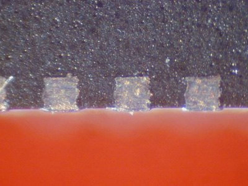
Figure 1. Tin plating slivers on a QFN.
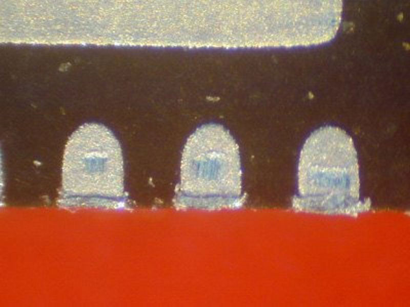
Figure 2. Burrs on QFN terminations.
These are often noted during microsectioning of joints, but have never been shown to be an issue. The method of component singulation, direction or tooling maintenance needs to be reviewed by the supplier. Reducing the insulation gap between terminations is a poor remedy and will be more of an issue with tighter pitches in the future.
These are typical defects shown in the National Physical Laboratory’s interactive assembly and soldering defects database. The database (http://defectsdatabase.npl.co.uk), available to all this publication’s readers, allows engineers to search and view countless defects and solutions, or to submit defects online. To complement the defect of the month, NPL features the Defect Video of the Month, presented online by Bob Willis. This describes over 20 different failure modes, many with video examples of the defect occurring in real time.
is a consultant at the National Physical Laboratory (npl.co.uk); martin.wickham@npl.co.uk. His column appears monthly.


Press Releases
- Seika Machinery’s SMI 2026 Webinar Series Continues with Focus on PCB Cleaning Before Solder Paste Printing
- Forwessun Expands Testing Capabilities through Strategic TRI Alliance
- Federal Electronics Expands Advanced Manufacturing Capabilities to Support Military and Aerospace Cable Assembly and Wire Harness Programs
- Altus Continues Irish Growth with Expansion of Engineering Team