

Incomplete PTH Reflow

Is poor stencil design the culprit?
This month we illustrate solder balling and incomplete reflow when reflowing through-hole components with pin-in-paste.
Solder balling pin-in-hole reflow (PIHR) close to the body of the connector suggests poor design of the stencil for this application (FIGURE 1). There is no standoff on the corner of this part, which may have permitted the paste to be displaced when the component was attached. There should always be free space around the paste deposit to permit placement and reflow, without contacting the paste.
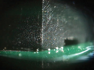
Figure 1. The presence of solder balls could mean poor stencil design.
In any PIHR process, the board and assembly with the connector must be correctly profiled to ensure all the solder paste reflows into the plated through-holes. The center of the connector on the board will be the coldest part during reflow. The closer the pin is to the body of the component, the cooler it will be, as shown in FIGURE 2. At the right of the image, there is successful reflow and hole fill. Moving from center to the left, the paste has not reflowed completely and has not reflowed adjacent to the connector body. Makes a nice x-ray image!
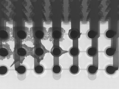
Figure 2. X-ray image showing paste reflowed at right but not at left.
We have presented live process defect clinics at exhibitions all over the world. Many of our Defect of the Month videos are available online at youtube.com/user/mrbobwillis.
is a process engineering consultant; bob@bobwillis.co.uk. His column appears monthly.


