LED Measurement Options at ICT
How to capture color values and light intensity.
The world of light-emitting diodes has seen a plethora of new applications in various devices, with vast improvements in energy efficiency, a wide range of color, longer lifecycles and so on.
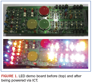
Today, almost every printed circuit board has an LED (Figure 1). For example, in the automotive industry, LEDs are used in headlights and dashboard displays. In networking they appear on servers, networks, or switch boards for IT troubleshooting. In the computer industry, LEDs are found on notebooks for wireless, sound adjustment displays, etc. Most consumer products – from printers and cellphones to rice cookers and washing machines – contain LED components.

This myriad usage gives us a fair idea of the breadth and depth of LED designs available today, with color and intensity acting as important visual indicators. But how can manufacturers ensure that the right LED is mounted on the PCB before it is shipped to the end-user?
Mounting an LED of the wrong color or intensity can cost in rework, labor, materials and so on. This has opened up a growing trend toward the strategic use of in-circuit test for measuring their color and intensity. LEDs need to be powered up during manufacturing test, and the ideal station to measure it would be ICT, as at this stage the tester is able to access the pins on the PCB and, hence, easily turn on the LED.
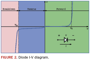
Traditional ICT on LED. ICT treats LED test as a forward bias diode test. After turning on the LED, ICT measures the LED forward bias voltage (Figure 2), which covers LED functionality. Unfortunately, it won’t tell you the color and intensity of the LED under test. However, there are ways to accomplish this.

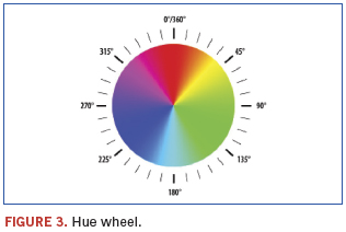
Fixture electronics. Most LED color and intensity measurements are conducted using fixture electronics. Any color on a spectrum is made by mixing red, green and blue (RGB). Every LED under test will have a set of RGB values. The hue is the measured location on the color wheel, defined via the degrees (Figure 3). The saturation of a color is determined by a combination of light intensity. All these values can be obtained through a light sensor, which converts the light signal into an electrical signal output.

Camera imaging. Another way to capture the color value is through a camera imaging process. Intensity is measured by the amount of light emitted by the LED under test. It is affected by environmental factors, such as the position or angle of the sensor or light pipe, the distance between LED and the sensor, etc. These signals are sent to the ICT for analog measurement, and upon frequency measurement, the tester will generate results showing the color and intensity of the LED under test. Because all the LEDs will be tested through analog test sequentially one by one, test time becomes a major issue in the production environment.
Yang Hua is technical marketing engineer at Agilent Technologies (agilent.com); hua_yang@agilent.com.
Press Releases
- News Zollner Continues to Expand Capabilities in Thailand
- Keiron Printing Technologies Appoints PIT Equipment Services to Support Revolutionary LiFT Technology Adoption
- Surf-Tech Manufacturing Adds New ViTrox V510i AOI to Strengthen Advanced Packaging Inspection
- Altus Supports Cambertronics’ SMT Process Upgrade with Koh Young SPI


