

Bare Board X-ray Inspection – Cracks and Breaks
 Use partial CT to reveal trace discontinuities at incoming inspection.
In last month’s column, I suggested using x-ray inspection equipment more typically used for the investigation and quality control of assembled PCBs to check bare boards ahead of their use in assembly. Such equipment is often already onsite and readily available to the assembler. The benefits of enhanced magnification and resolution this equipment can usually offer toward inspection of representative bare boards ahead of assembly is, I contend, an opportunity to provide additional confidence that all is well in the bedrock of PCBA. Furthermore, the cause of any future issues, if they occur, can be more easily narrowed down to the assembly process, design or components. The example I gave related to the possible issue of poor drilling quality in the board vias and how, in x-ray images, the plating variability can be readily seen, especially if the via is buried within the board and optical inspection is not possible. Variable plating quality, however, such as voiding in the central termination of a QFN (see “QFN Inspection: Don’t Forget the Edge!” December 2018 column), can often be relatively obvious for an operator to see when it occurs in the x-ray image such that if it is not present and all looks consistent and appropriate, then other subtler issues may not be considered fully, or missed entirely.
Such is the case with the example I showed last month. The oblique-angled x-ray image of the via with plating variation had subtler issues associated with it that only become apparent with higher magnification views and the availability of presenting sensitive grayscale variation in the image (FIGURE 1). In Figure 1 there are also some faint lines indicating cracks in the plating (highlighted). This could indicate delamination within the board. Therefore, even if the plating variation is deemed acceptable, the more serious issue of a potential break in the continuity may be missed. In part, this could be caused by the plating variation almost tricking the eye into not seeing the other flaw(s). Even in the situation where the plating variation is good and consistent, however, observing breaks in the via is tough to do (FIGURE 2). In Figure 2, the plating variation is much more consistent. The presence of faint lines at the top and bottom trace interconnections, however, is of sufficient concern to warrant additional examination for potential delamination within the board. Note: Not all x-ray equipment may be able to resolve such subtlety. This will depend on the x-ray tube, detector, sample manipulation and image enhancement software functions of each respective system. Running test bare board samples (ideally with and without known faults) is very important to know the limitations of your x-ray equipment.
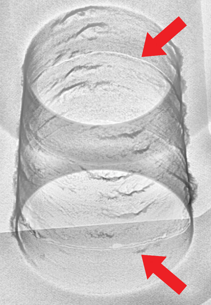
Figure 1. Oblique-angled 2-D x-ray image of via with plating variation down the barrel and the presence of cracks in the plating (highlighted).
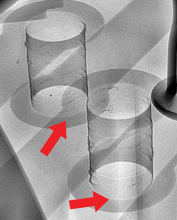
Figure 2. Oblique-angled 2-D x-ray image of vias where possible breaks at the track terminations are seen (highlighted).
Figures 1 and 2 show the importance of access to a library of good and bad example references relevant to the manufactured products in order to train personnel, as well as compare future suspect issues to confirm the analysis.
An additional opportunity for using x-ray inspection on bare boards is to identify cracks in internal and external copper traces. Looking for such issues in a 2-D x-ray image, where all board layers overlap, can be difficult. Even using oblique views may not separate the overlap sufficiently to assist. This is where the PCT technique, available on some x-ray systems (see “CT or PCT: That is the Question!” June 2018), can provide 3-D analysis and help declutter the analytical picture.
The results of such capabilities are shown in FIGURE 3. Partial CT (PCT) can be used at any point in the board to provide laminography, or 2-D x-ray slices, over a defined field of view into its z-depth. This can be achieved without cutting the board down to a smaller size. This permits PCT to be used nondestructively to view the individual trace layers without being overlapped, or obscured, by others (Figure 3). Unfortunately, I did not have a “good bad” example showing an actual crack, but I suggest that if a trace discontinuity were present, it would be much more obvious at the individual PCT slice level. Nonetheless, this image does show the misalignment of the vias with the traces particularly well, with the vias offset with respect to the center of the termination.
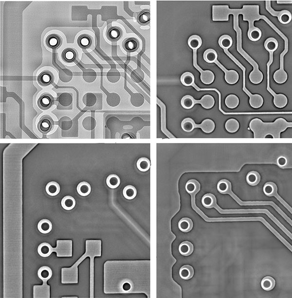
Figure 3. Top-down 2-D x-ray image (top-left) of bare board with three PCT slice layers at different track levels. Misalignment of the vias with the center of the terminations can be seen in the righthand slice layers.
Bare board problems may not be at the top of the list when it comes to defect and failure analysis. That does not mean they should be ignored, however. Use the additional functionality of x-ray equipment you may already have to check subtler issues that may occur on bare boards.
Au.: Images courtesy Peter Koch, Yxlon International.
, is an expert in use and analysis of 2-D and 3-D (CT) x-ray inspection techniques for electronics; dbc@bernard.abel.co.uk.


Press Releases
- Seika Machinery’s SMI 2026 Webinar Series Continues with Focus on PCB Cleaning Before Solder Paste Printing
- Forwessun Expands Testing Capabilities through Strategic TRI Alliance
- Federal Electronics Expands Advanced Manufacturing Capabilities to Support Military and Aerospace Cable Assembly and Wire Harness Programs
- Altus Continues Irish Growth with Expansion of Engineering Team