

Current Issue
Shielding Effectiveness of Polyimide Tape during Rework
A study shows several materials are superior to the commonly used Kapton.
A variety of temperature-sensitive components such as aluminum and tantalum ceramic capacitors, crystals, and plastic-bodied components such as connectors may be damaged during the rework process. These devices have to be protected from exposure to heat during rework. Otherwise they can become damaged, showing either visible or “hidden” damage. In addition, these components’ long-term reliability may be impacted by this exposure to heat, even though their immediate outward appearance may not indicate this. While these components may be able to withstand the peak temperature of 260°C as defined in J-STD-002,1 there may be medium- and longer-term impacts to their reliability.
Our work examined the current state of shielding options for protecting neighboring devices during rework. This was followed by a short study that compared and contrasted the shielding effectiveness of the most common materials.
The increased liquidus temperature of lead-free solders has driven processing temperatures into areas where sensitive components have significant body temperature and time limitations. (J-STD-075 is the standard for maximum time/temperature exposure for all non-semiconductor devices.)
Solutions
The objective of an effective shield material in the rework process is to somehow protect enshrouded susceptible components from both radiant and convection heat. One type of thermal energy is known as radiant heat. It is the major source of heat transfer in the rework process, and its energy is transferred in the form of infrared waves. It travels at the speed of light and is either transmitted through, absorbed into, or reflected by any material it comes in contact with. Convection is another process by which heat can be transferred from the outside environment to a PCB. Heat transfer occurs at a higher rate across materials of high thermal conductivity than across materials of low thermal conductivity. Correspondingly, materials of high thermal conductivity are widely used in heatsink applications, and materials of low thermal conductivity are used as thermal insulation. Thermal conductivity of materials is temperature-dependent. The thermal conductivity of the materials used in the study is listed in TABLE 1.
Table 1. Thermal Conductivity of Common PCB Rework Shielding Materials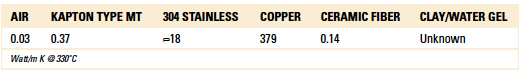
Not only can heat be transmitted through space to components in the surrounding area, absorbing the radiant energy, but through the PCB itself, through the directed rework heat. The bottom-side heating process can radiate heat throughout the board, otherwise known as “conduction.” The greater the surface area of the copper, the greater the ability to conduct heat through the conduction mechanism. There is no effective manner to stop this phenomenon; it is a function of the material properties of the PCB, and it’s associated within its layout and geometries.
A variety of materials are typically used for shielding components near the rework area. Stainless steel sheet metal shields are designed to shield a component from absorbing excessive heat either by dissipating, reflecting or simply absorbing the heat. The physical properties of stainless steel’s reflectivity and emissivity, thermal conductivity and specific heat capacity make it the ideal material for the fabrication of heat shields.
Copper tape permits the shield to be flexible; therefore, it can be easily applied to a PCB. The adhesive side permits it to adhere to a board surface and stay tacked down. The tape is relatively inexpensive and is a reasonable material choice for a heat shield. Kapton tape is the most commonly used for masking areas on a PCB. Historically used in the wave soldering and conformal coatings areas, Kapton tape has made its way to the PCB rework area. While it does work well to hold a thermocouple to the board, it is a poor thermal insulator.
Clay/water-based gel, while unknown in the electronics industry, has been used in welding applications due to its extreme resistance to heat. The product is easily applied and, due to its consistency, able to work its way into small spaces. After heat is applied, the water in the product begins to evaporate until a layer of gray clay is deposited on the circuit board. This clay is not as effective a shield as the wet product and should be reapplied once the water “burns off.”
Specialty ceramic fiber non-woven shields, previously relegated to aerospace and other demanding industries, offer a low thermal conductivity and low bio-persistence material (meaning that if the fibers are inhaled, they’re eliminated from the body within days). This material can be used at 1,100°C continuously, with excursions to 1650°C. This ceramic fiber material offers several advantages, including high-temperature stability, low thermal conductivity, high heat reflectance and the ability to be easily wrapped and cut to shape. Since these materials are compressible, they can also be easily fit between components, making it an ideal material for shielding.
To determine shielding effectiveness of various materials, a controlled heat source, simulating a rework process, was placed on a reference site on a 10-layer PCB. A BGA location, U3, was used as a reference site location to 235°C to within 5°C. The distance from this IC reference temperature to three separate components, a speaker (30.95mm), a battery (9.73mm) and connector (6.14mm) was measured (Figure 1). The maximum temperatures were observed during the simulated rework heat cycle at each of these locations. Between each measurement, the board was brought back to room temperature. The thermocouples were embedded at each of the device of interest locations, as well as at the control rework location. The thermocouples were connected to an ECD M.O.L.E. scan thermal profile scanning system that recorded the measurements (FIGURE 2). Five measurements were taken for each type of shielding material (FIGURE 3); notes were taken as to the suitability of the material to withstand further heat cycles, and the locations documented via photographs. Testing results are tabulated in FIGURE 6.
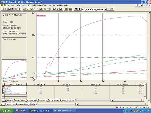
Figure 1. Thermocouples were placed on a speaker, connector, battery, and IC reference site.

Figure 2. Time vs. temperature at various points on test board, ceramic fiber shield material.
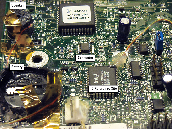
Figure 3. Shield materials used in study.
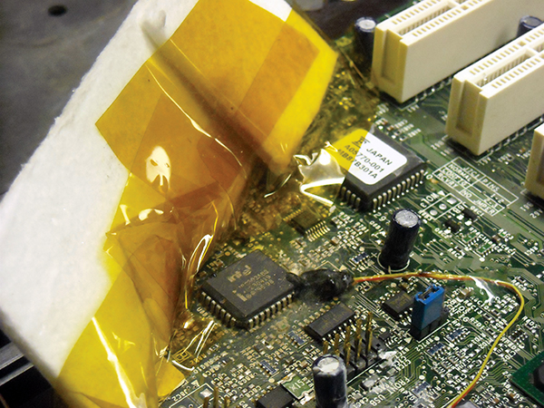
Figure 4. Ceramic fiber heat shield was then taped using Kapton tape to the board to protect the components.
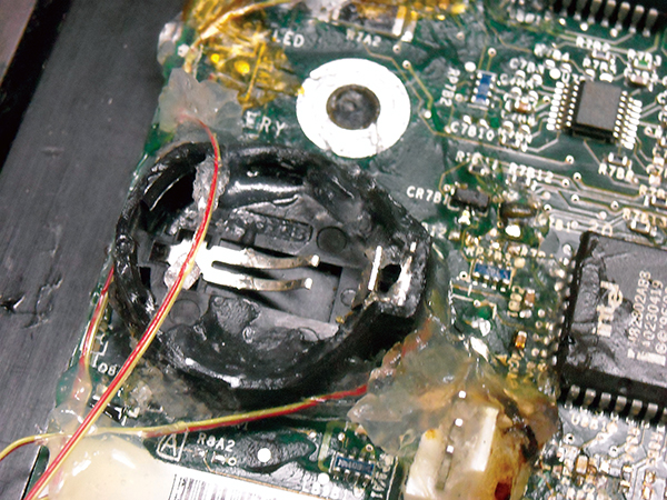
Figure 5. View of clay/water gel applied to the board.
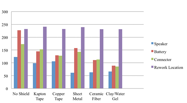
Figure 6. Maximum temperature in degrees C for various shielding materials at select locations on a PCB.
Conclusions
Through repeated measurement of maximum outlying component temperatures during the reflow process, Kapton tape proved worst in terms of effectiveness of the typical shielding materials tested. Surprisingly, the clay/water gel, which is unproven in the electronics industry in terms of material compatibility and remnant ionic residue, was determined to be the best performing heat-shield material. More testing is needed, as it is currently an unproven material. The second-best shield material that can be applied with polyimide tape was the ceramic fiber material. The next closest performing materials were, in order, copper tape, stainless steel shields, and finally Kapton tape.
References
1. J-STD-002, “Solderability Tests for Component Leads, Terminations, Lugs, Terminals and Wires,” June 2013.
2. Charles Mauney, “Thermal Considerations for Surface Mount Layouts,” Texas Instruments.
3. Jakob Dieterle, “Heat Management in Printed Circuit Boards,” Project Report 2010 MVK160 Mass Transit, May 11, 2010.
is a J-STD-CIS and a student at the University of Miami (OH). is president of BEST Inc. (solder.net); bwet@solder.net.


Press Releases
- Kitron Secures EUR 37M order for Next-Generation Tactical Communication Equipment
- Scanfil Comparison Figures for Updated Customer Groups
- Javad EMS Invests in Inovaxe Smart Storage Carts to Streamline Material Management and Boost Production Efficiency
- ViTrox Announces Strategic Partnership with High Tech Solutions (HTS) to Strengthen Presence in Argentina