2005 Articles
Mean Green Corrosion
Avoiding residues on ImAg boards selectively soldered with no-clean flux.
No-clean fluxes are designed to be protective and insulative of boards, but in selective soldering fluxes often fail to become fully complexed, leaving harmful conductive residues on the board. This effect can be seen on all types of board finishes, but ImAg is particularly sensitive to the aggression of no-clean flux residues.
 |
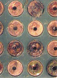
| FIGURE 1: No-clean flux boards before rescue cleaning ... |
 |
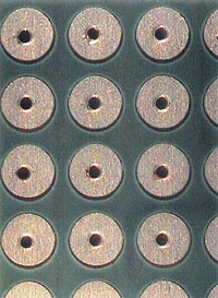
| FIGURE 2: ... And after. |
In one case, a customer was assembling ImAg-finished boards using a VOC-free water-based no-clean flux. Failures were occurring around selective soldering sites, which showed a green corrosion (Figure 1). We were sent seven assemblies, four bare boards and a flux sample for failure analysis. Using the C3 tool, we extracted localized samples around the failure sites. These samples were then used for ion chromatography analysis in a Dionex ICS 2000 system per IPC-TM-650 2.3.28 to identify and quantify ionic residue species present. Upon analysis, these sites showed marginal-to-low levels of chloride, but some levels were high enough to indicate a contribution to the attach on the silver and copper. The levels were not high enough to be the primary cause of the green corrosion. These sites did, however, show very high levels of weak organic acid (WOA) flux residues and a water carrier. These residues are very hydroscopic, and are the primary cause of the visible copper chloride corrosion. We also tested the pH around the areas of corrosion. On a failed area pH measured 1.7, while on a reference area pH measured 7.7. This shows how the typical residues on ionically clean areas of the board are neutral, while the no-clean flux and water residues leave a strong acid on the silver finish.
Based on the findings and our experience in developing cleaning protocols for no-clean assemblies, a rescue cleaning protocol was developed to recover the boards. Using 10% saponifier and 90% DI water with regular in-line cleaning, we removed the corrosion and decreased ionic residue levels to within the parameters for long-term field performance.
One suggestion to prevent this situation is to add a secondary heating step for areas protected by the pallet during selective soldering to ensure that all the VOC-free no-clean flux gets volatilized. It could potentially help to switch to an alcohol-based no-clean flux, but a secondary heating step would still probably be needed and the alcohol-based flux may not be sufficiently aggressive to optimize solderability. For the secondary heating step, we recommend a 4 or 5 zone reflow oven with temperatures above the 150°C required for flux activation for 30 seconds.
Adding a post-wave thermal step may also help. This can be done either by baking the boards or running them through a reflow oven, making sure not to exceed the flux activation temperature. If baking, bake at 125 to 130°C for half an hour within three hours of wave soldering. The more cross-flow ventilation the oven has, the better the volatilization of flux trapped in vias.
For the reflow option, permit the boards to dwell at 150°C for 20 to 30 seconds (similar to a glue cure profile) with a very gentle thermal increase and cooldown. Adding this step permits the flux and water carrier trapped between board and pallet to fully activate and will drive off the water carrier so that only benign, insulative no-clean flux residues remain.
In addition, cleaning the pallets prior to use to decrease flux buildup will help with this manufacturing process. In this instance we used Envirogold Envirosense 816 saponifier at 10% in a 140°F bath, and then steam-cleaned the pallets with a PDQ Minimax 2 steamer (Figure 2).
Based on these steps, this customer was able to remedy the corrosion problems and prevent future occurrences of the copper chloride green contamination.
Terry Munson is with Foresite Inc. (residues.com); tm_foresite@residues.com. His column appears monthly.
Press Releases
- Surf-Tech Manufacturing Adds New ViTrox V510i AOI to Strengthen Advanced Packaging Inspection
- Altus Supports Cambertronics’ SMT Process Upgrade with Koh Young SPI
- Ben Maulorico joins Insight Polymers & Compounding as business development manager
- Strengthening SEMI Business (Semiconductor Back-End Process) in the European Market


