Flux Impact on Void Reduction in Bottom Terminated Components
Can improved flux coatings on solder preforms reduce voiding?
Void reduction is a critical challenge in electronics assembly, especially for bottom terminated components (BTC) such as QFNs (quad flatpacks no-leads). Excessive voiding inhibits heat transfer between the thermal pad on the QFN and the PWB pad. Flux-coated solder preforms have been shown to significantly reduce voiding.1 Here, the investigators studied the effects of flux coating improvements on voiding.
Sample preparation and experimental procedure. Eutectic SnPb or SAC 305 solder preforms were placed between two ENIG coated 1.25" x 0.375" x 0.008" copper-oxidized and non-oxidized substrates and reflowed in air (Figure 1). To ensure statistical confidence in the results, 30 samples were evaluated at each experimental condition. Half the experiments were performed with a typical flux coating (A) and the other half with a new flux (B). No mechanical pressure was used on the substrates during the ramp-to-peak reflow processes. A statistical comparison of the voiding performance of the two fluxes was then performed.

Figure 1. In the experiment, two ENIG-coated copper substrates were reflowed with flux-coated solder preforms. Half the copper substrates were oxidized.
Flux B is a halogen-free flux in 1% formulations.
The typical flux coating formulation (A), also at 1% concentration, produces inconsistencies and gaps in the flux coating, as seen in Figure 2. Gaps and inconsistencies often result in more voiding.
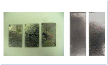
Figure 2. Gaps and inconsistencies in Flux A (left) will often result in more voids compared to Flux B.
All samples were processed in an air reflow, ramp-to-peak profile. Data were collected to measure the void content after reflow using x-ray imaging
(Figure 3).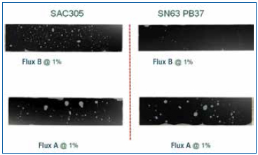
Figure 3. Flux voiding was measured from the x-ray images. Note the much lower voiding level for Flux B.
Data Analysis
SAC 305 non-oxidized substrates. All experiments were performed with 1% flux formulations. A boxplot of voiding data for the non-oxidized SAC 305 substrates for both flux types is shown in Figure 4. The mean voiding value for the substrates treated with Flux B was 1.39%, whereas the value for substrates treated with Flux A was 2.79%. Performing a two sample t-test analysis indicated that Flux B produced fewer voids than Flux A with a statistical confidence of >99.99%.
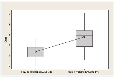
Figure 4. Boxplot of voiding data for non-oxidized SAC 305 substrates coated with Flux A and Flux B. Statistical confidence: >99.99%.
SAC 305 oxidized substrates. A boxplot of the voiding data for the oxidized SAC 305 substrates for Flux A and Flux B is shown in Figure 5. The mean value for the substrates treated with Flux B was 1.79%, whereas the mean value for substrates treated with Flux A was 2.71%. Performing a two sample t-test analysis indicated that Flux B produced fewer voids than Flux A with a statistical confidence of >99.9%.
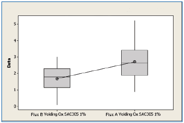
Figure 5. Boxplot of voiding data for oxidized SAC 305 substrates coated with Flux A and Flux B. Statistical confidence: >99.9%.
SnPb non-oxidized. A boxplot of voiding data for the non-oxidized SnPb substrates for both fluxes is shown in Figure 6. The mean voiding value for the substrates treated with Flux B were 0.327%, whereas the substrates treated with Flux A was 1.89%. Performing a two sample t-test analysis indicated that Flux B produces fewer voids than Flux A with a statistical confidence of >99.99%.
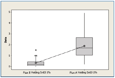
Figure 6. Boxplot of voiding data for non-oxidized SnPb substrates coated with Flux A and Flux B. Statistical confidence: >99.99%.
SnPb oxidized. A boxplot of voiding data for the non-oxidized SnPb substrates for both fluxes is shown in Figure 7. The mean voiding value for the substrates treated with Flux B was 0.197%, whereas the value of the substrates treated with Flux A was 2.29%. Performing a two sample t-test analysis indicated that Flux B produces fewer voids than Flux A with a statistical confidence of >99.99%.
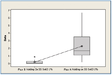
Figure 7. Boxplot of voiding data for oxidized SnPb substrates coated with Flux A and Flux B. Statistical confidence: >99.99%.
Summary
Void data are summarized in Table 1. In all cases, there is a strong statistical confidence that Flux B performs better than Flux A. The new Flux B is halide-free and improves wetting. Flux B coats the solder preform more uniformly to further improve wetting. These features significantly reduce voiding when preforms are used with BTCs such as QFNs. Additionally, Flux B leaves less flux residue.

Table 1. Voiding Data Results
References
1. Seth Homer and Dr. Ronald C. Lasky, “Minimizing Voiding In QFN Packages Using Solder Preforms,” IPC Apex, February 2012.
Seth Homer is assistant product manager engineered solders, thermal materials and NanoFoil preforms at Indium (indium.com); shomer@indium.com. Dr. Ronald C. Lasky is senior technologist at Indium.
Press Releases
- Smartsol and Koh Young Technology Announce Strategic Partnership for the Mexican Market
- RBB Systems Boosts Manufacturing Capabilities with Equipment Upgrades for 2026
- 11th Class of Engineering Interns Begins Forging Success at Hyrel
- Rocka Solutions Announces 2026 Rockin’ Roundtable: An Interactive Discussion on What Really Drives SMT Printing Performance


