

Circuits Disassembly: Materials Characterization and Failure Analysis
A systematic approach to nonconventional methods of encapsulant removal.
An unfortunate reality is that the circuits we assemble do not always perform as expected. Failure analysis is frequently needed to find root causes. In such cases, it is common to encounter components encapsulated with materials that must be removed to permit inspection. While “decapsulation” methods are well documented, with many guides available to help with products and “recipe” selection for concoctions to remove encapsulants (ASM Microelectronics Handbook, Dynaloy data sheets, etc.),1 the analyst will encounter materials in which standard methods, such as use of fuming nitric, sulfuric acids or commercial deprocessing products, fail to produce the desired outcome.
Most often, this poor outcome arises because the chemicals used to remove encapsulants also attack the materials of interest. For example, using nitric acid on sites composed of copper wire bonds results in almost no chance of the copper remaining unmolested for further analysis. This highlights the “magic bullet” misconception – belief that a chemical can be found that selectively attacks only the materials wanted, while not altering materials of interest.
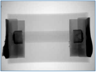
Figure 1. Overall resistor construction revealed by x-ray imaging.
Methods such as breaking parts simply by fracturing or cleaving, burning away materials in a furnace, use of unconventional chemicals, or mechanical methods can often overcome standard methodology limitations and permit successful removal of encapsulants, while maintaining the integrity of the materials of interest. A systematic approach to such challenges and examples in which the Raytheon Failure Analysis Lab in McKinney, TX, addressed some of these are highlighted here.
In all things, it is generally a good idea to think about how to proceed before actually undertaking a task. In the case of decapsulation, several fundamental questions should be asked:
- What is the composition of the materials to be removed?
- What is the composition of the materials that are expected to be revealed?
- What are the properties of the materials?
- How will the materials respond to the decapsulation process?
The answers are crucial with regard to choosing the proper methods to remove the encapsulation while preserving the materials of interest. Labs that perform such procedures on a regular basis are certainly aware of such issues and likely have common procedures in place. A typical protocol might follow a procedure such as:
- Identify material compositions from data sheets or analysis in the lab. (FTIR spectroscopy is a quick method for determining most material classes of interest.)
- Consult a materials chart that provides guidelines as to proper procedures. For example, many suppliers of decapsulating agents provide charts that indicate which of their products to use for each material type.
- Follow proper procedures, with safety a key concern, and monitor the components at regular intervals to achieve the desired penetration, while maintaining the exposed materials’ integrity.
As mentioned, such procedures are typical and apply to most applications. However, the analyst also encounters examples in which standard procedures will not work and creativity is needed in planning the proper exposure route. The remainder of this article will focus on a few such examples faced by our lab and highlight the rationale behind these often unconventional approaches.
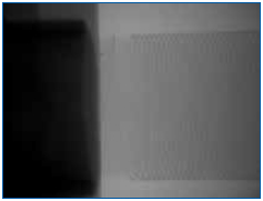
Figure 2. No fractures in the element or issues related to the end cap weld joint could be resolved.
Why Not Burn It Off?
It may seem counterintuitive that burning away material is an acceptable approach; after all, such a method is aggressive, seemingly difficult to control, and not very selective. However, in some cases, in which the goal is the burning away of combustible materials to reveal noncombustibles such as metals, the approach can overcome limitations of other more traditional techniques. For example, if the purpose of the decapsulation is to reveal fine metal features such as wires of a resistor, small bond wires, and others, the use of strong acids such as nitric often results in dissolution, or at least attack, of the metals of interest.
In the following example, multiple wire-wound resistors were failing in an open condition once installed on an assembly and exposed to environmental testing. X-ray analysis could not resolve an open condition in the nickel-chromium element. Therefore, a method was devised to selectively remove the encapsulant without affecting the fragile element, thus permitting further detailed inspection.
The package design was such that the wire element was wound over an alumina core with a heavily glass-filled encapsulant. Such a design seemed ideal for furnace removal of the encapsulant, as the materials to be revealed are capable of withstanding exposure to 500˚ to 600˚C and flames resulting from the burning of the epoxy. In this case, the leading concern was to avoid mechanically disturbing the delicate wires during the process. To ensure the approach was reasonable, a known good component was subjected to the proposed methods and found to pass electrically on decapsulation, an indication that the method did not damage the element.
The method was composed of the following steps:
- Packages were exposed to 500˚ to 600˚C in an appropriate furnace. Samples were monitored to determine complete combustion of the packaging epoxy (about 5 min).
- Packages were examined for completeness of the process. In such examples, very close control of the heat can overcome the problem encountered: the glass filler fused, forming a secondary layer that needed to be removed. Ideally, if the combustion heat is maintained at a sufficient temperature to burn away the polymer but not fuse the glass, the filler can be gently, mechanically removed. Unfortunately, in many cases, such as this example, the glass forms a secondary material that must be removed before the inner package surfaces are revealed.
- The fused glass was digested using hydrofluoric acid. After burning away of the epoxy, the package was placed in concentrated hydrofluoric acid with stirring, and monitored for complete removal of the glass. This is a weak acid that is very selective for glasses and very mild to most all metals. (There are exceptions.)
Figure 3 shows that the resistive element appears to be disturbed in areas adjacent to the fracture site indicated; this is due to a lack of tension in the wires at this region (due to the fracture) coupled with gentle agitation of the wires in the hydrofluoric acid. Regardless, the fracture site was easily identified and characterized.
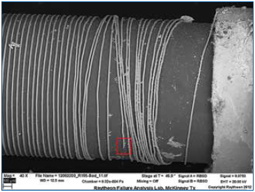
Figure 3. Wire revealed on alumina core.
Figure 4 reveals features that indicate the wire was corrosively attacked. Additional failing samples were evaluated using the same deprocessing methods, and similar features were identified at the fracture locations. These were always in close proximity to the end cap terminations; this suggested that a contaminant may have “wicked” in during processing or environmental exposure. Although this deprocessing technique was useful in identifying the failure mode (corrosive attack), root cause had not been established, and any possible chemical agents that may have contributed to the corrosion were removed by the procedure.
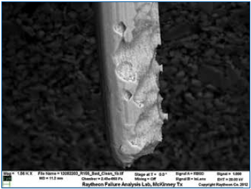
Figure 4. SEM figure of Nichrome wire at fracture site.
In addition to the example cited, we have successfully deprocessed several parts using the furnace approach at such times when it is applicable. For example, in another case, very small aluminum wires encapsulated in a soft urethane coating were not revealed by x-ray examination. Burning away the potting in the furnace allowed us to successfully characterize the wires.
Mechanical Methodology to Minimize Chemical Exposure
Purely mechanical deprocessing methods were employed to test the chemical “wicking” hypothesis presented in the previous example. In such a process, no chemicals can be used that may contaminate the device or even remove suspect contamination. In this analysis, we had the luxury of multiple failing samples to utilize different complementary deprocessing methods. A subset of the failing devices was mechanically deprocessed using a cleaving tool to separate the molding and expose the element. Obviously, this technique was never intended to preserve the condition of the fragile element.
Isopropyl alcohol extracts of contaminants on the exposed element were captured and evaluated using GC/MS (gas chromatography/mass spectrometry) methods. The presence of glycerin was identified on all failing devices, a good target compound indicating the presence of water-soluble fluxes. Consultation with the supplier revealed that they did indeed use a water-soluble flux with these devices. As a result, a good device was similarly deprocessed and exposed to the flux with power applied to test the assumption that such exposure led to the open. Similar corrosive attack was noted. Corrective actions included changing to a more benign flux.
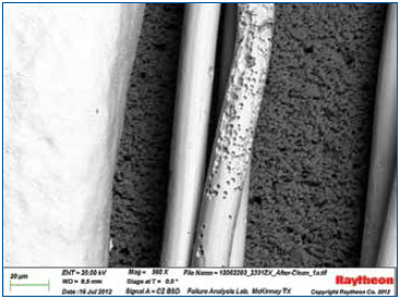
Figure 5. Corrosive attack resulting from the wire being exposed to water-soluble flux while powered.
This example highlights the use of hydrofluoric acid for digestion of glass, much like the previous example, but is used on a package that traditional methods were also employed. The semiconductor package displayed in Figure 6 contains stacked die and is configured with an interposer board. Upon visual inspection, the molding compound appeared to have a shiny smooth surface. (FTIR analysis showed this to be a heavily glass-filled epoxy.) To decapsulate, the package was submitted to the traditional methodology using fuming nitric acid. The molding compound displayed only limited removal using this approach. This was determined to result from the extremely high glass content in the encapsulant. (In such cases it is perhaps more useful to think of such materials as glass with polymer binder than a glass-filled polymer.) While the nitric acid was effective at removing the polymer, the glass at the outermost exposed layer concentrated, forming a barrier unaffected by nitric acid. It was decided a multi-step process alternating between nitric and hydrofluoric acids would address this issue. After the nitric acid ceased to be effective, 49% hydrofluoric acid was applied to the top layer for a minute or so. After this, the hydrofluoric acid was rinsed away and nitric acid was reapplied. This sequence was repeated three times, and decapsulation was successful.
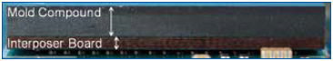
Figure 6. A heavily glass-filled epoxy encapsulant.
The Problem with Silicones
Silicones are ubiquitous materials used in a multitude of applications, including coatings, underfills, thermal transfer compounds, adhesives, and others. It is desirable in many instances that such materials be removed from components during deprocessing. One of the most common methods is to soak these materials in solvents such as xylenes or hexanes, swelling and softening them for ultimate mechanical removal. This presents obvious issues when deprocessing delicate assemblies, such as mechanically destroying fine features during the removal process. Also, while a few silicone removal products are available from commercial sources, these rely on corrosive additives that digest the silicone rather than simply dissolving them. Such aggressive materials may compromise sensitive materials, and swelling often still occurs.
While we would like to claim credit for the following solution (we cannot), we have found scarce reference to a method reported by Sachdev.2 While the focus of the referenced article is silicone adhesives, we have found it equally applicable to all silicones we have tested, including condensation, and addition cure materials, including thermal transfer media, pottings, and “RTVs.”
We found that application of a solution of 1% tertabutylammonium fluoride (TBAF) in propylene glycol methyl ether acetate (w/v), as described by Sachdev, heated from 50˚ to 90˚C with gentle stirring works exceptionally well to remove silicones and not damage sensitive materials. (Higher heat and solutions with greater concentrations of TBAF proved to accelerate the digestions.)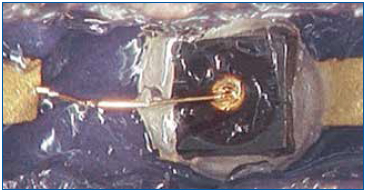
Figure 7. Bond wire prior to silicone removal.
In the following example, a silicone potting covered very fine bond wires of a diode in a hermetic package. The goal was to examine the diodes and perform a bond-pull on the wires to document possible degradation modes after highly accelerated life testing (HALT). The typical methods of removing the silicone invariably caused dimensional changes in the silicone, which imparted an undesirable stress on the wires.
The new method was tried on a few test samples, and the results were excellent. No damage or deformation was observed. Bond-pull results compared favorably with the devices under test.
Another example of this technique that demonstrates its value is the failure investigation of a complex product with multiple layers of material. The failure scenario suggested the likelihood of broken bond wires. A partial view of the component is shown in microsection (Figure 8). The materials in this view are labeled, and the objective was to expose the wires for evidence of fracturing somewhere along the wire or at the bonds. Sectioning in silicone to reveal fine features cannot achieve this objective. Using traditional methods, once the silicone is exposed, the approach leads to swelling, cracking or other dimensional changes that could induce the very same damage in the bond wires that we are attempting to uncover.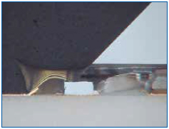
Figure 8. Cross-sectional view of device.
This technique was used to dissolve the silicone after the epoxy over-mold was removed. This was first tried on a known-good and new test sample. Results are shown in Figures 9 and 10. There was no deformation of the bond wires. Subsequent attempts on failed samples allowed us to confirm fine heel fractures in the bond wires. Finally, Figure 11 shows how the method permitted fine details of the exposed bond wires to be recorded.
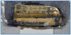
Figure 9. The silicone-encapsulated wires are visible after the epoxy was removed.
Figure 10. Wires shown after silicone removal. No deformation or damage was detected on the test samples, and heel fractures were found on the failed samples.
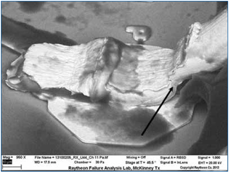
Figure 11. SEM of the wire bond shows that the silicone encapsulation has been sufficiently removed to permit inspection of fine details. Crack initiation is visible in the neck-down region (heel) of the wire.
Standard decapsulation methods are not always applicable, and the analyst must devise approaches to circumvent their limitations. While certainly not exhaustive, a few examples that provided unique challenges to our lab were highlighted. These were selected to show that, at times, unconventional solutions to such problems, when devised with materials variables in mind, can often prove quite effective.
References
1. The SAE G19A Test Laboratory Standards Development Committee will soon be releasing a decapsulation standard. Also, a web search of the terms “decapsulation of electronic components” will result in many additional references.
2. Krishna G. Sachdev, Ph.D., “Removing Cured Silicone Adhesive from Electronic Components," Solid State Technology, October 2010.
W. John Wolfgong, Ph.D., is a chemist; Jana Julien is a failure analyst; Jason Wheeler is a failure analysis engineer, and Joe Colangelo is a principal failure analysis engineer at Raytheon Space and Airborne Systems, Component Engineering Department (raytheon.com); wolfgong@raytheon.com.


Press Releases
- Forwessun Expands Testing Capabilities through Strategic TRI Alliance
- Federal Electronics Expands Advanced Manufacturing Capabilities to Support Military and Aerospace Cable Assembly and Wire Harness Programs
- Altus Continues Irish Growth with Expansion of Engineering Team
- Kevin Castonguay Joins MicroCare as Senior Director of Marketing