

Coming Up Short

Consider pin replacement to ease bottom-side soldering.
This was a PCB assembly challenge. The customer’s bill of materials called for a through-hole header part to be installed on a circuit board, a mixed technology (SMT and PTH) assembly. A problem became immediately apparent with the first PCB that our operators began to assemble; this was a very thick circuit board (12.15mm thick), but the part specified and received did not have terminal pins long enough to protrude all the way through the PCB to other side (bottom side) (FIGURES 1 and 2).
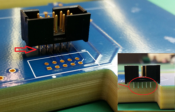
Figure 1. Original part’s through-hole pins are not long enough to go through the board and be soldered from the bottom side.
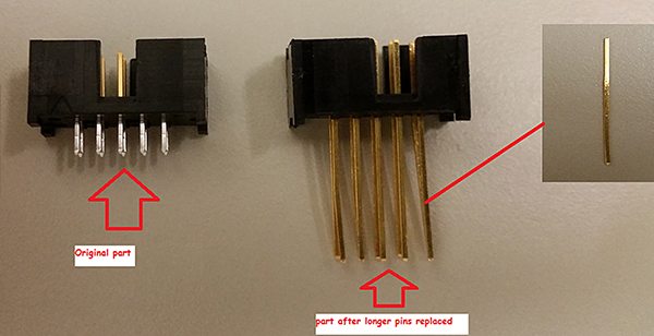
Figure 2. Cross-section of PCB showing penetration depth of part’s original pins.
Obviously, we needed the pins to penetrate all the way to the bottom side and protrude so they could be properly soldered using wave or selective soldering techniques.
What to do?
In this instance, a replacement part with pins of sufficient length simply wasn’t available. The easiest solution (although labor-intensive) required manual removal of all the original pins from the part, and their replacement with longer pins of sufficient length, to form good and robust solder joints on the bottom side of the PCB assembly (FIGURE 3).
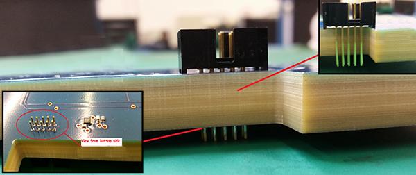
Figure 3. Side view showing new pin length (inset: bottom side view).
Once the longer pins were added, it became a simple matter to reinsert the through-hole header part and solder it in place from the bottom. The parts of the pin protruding from the solder joint could then be dealt with the same way as any other soldered through-hole pins.
is chief executive officer of Rush PCB, a printed circuit design, fabrication and assembly company (rushpcb.com); roy@rushpcb.com.


Press Releases
- Altus Group Invests in Major Headquarters Expansion to Showcase Complete Turnkey Manufacturing Capability
- ViTrox Americas Welcomes Eric Cruz as Technical Support Engineer
- ECD Strengthens Engineering Team with New Software Development Hire
- ViTrox Americas Welcomes Doug Ennis as Senior Field Applications & Service Engineer