

QFPs: An Inspection Achilles’ Heel?
 Void size and location can predict future failures.
Perhaps quad flat packages are not as fashionable a package choice as they once were because of their limited I/Os compared to BGAs, but they continue to be a staple in electronics (FIGURE 1). As such, they are still a source of problems to assemblers. With their typical gull wing joint style, located on the outside of the package rather than beneath it, these devices can be inspected optically. This can identify some issues that may arise but, as with other packages, if you can’t see the problem optically, it does not mean it is not there! Therefore, x-ray inspection of QFPs can complement any optical inspection, not only by helping confirm issues raised optically, but also providing wider fault coverage through identifying and helping mitigate a range of optically invisible issues that QFPs can provide.
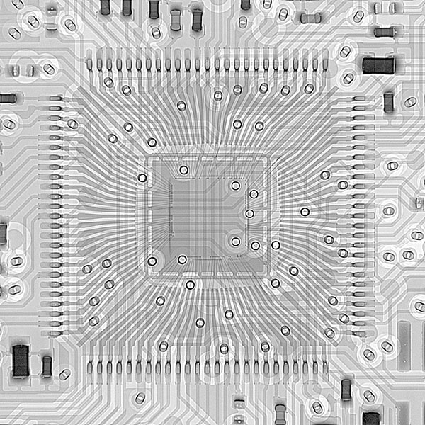
Figure 1. X-ray image of QFP from the top down.
The absence of solder (an open joint) or a lifted lead in the QFP may well be detected optically, but as the difference between a good and bad joint becomes subtler, successful optical analysis, especially when using only a top-down view, may be compromised. This is where x-ray inspection can help. As with most x-ray image analyses, looking for joint shape variation, which indicates a lack of consistency over equivalent joints, will identify where issues may be occurring (FIGURE 2). Figure 2 shows magnified, top-down views of some QFP gull wing joints. The problem joint is clearly different from the rest. When viewing from an oblique angle (FIGURE 3), the lifted lead in Figure 2 is highlighted, and its joint shape variation is even more striking than in the top-down view.
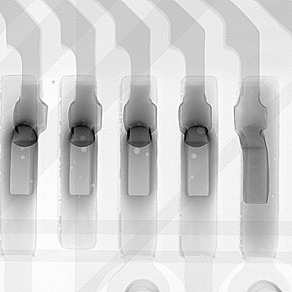
Figure 2. Top-down x-ray images of gull wing joints in a QFP.
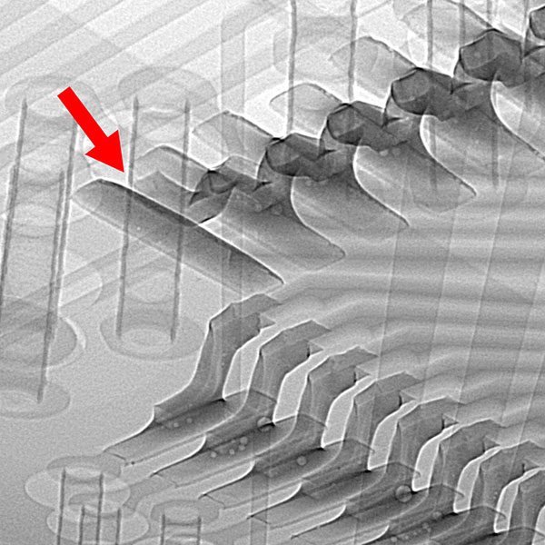
Figure 3. Oblique x-ray image of QFP gull wing joints. Lifted lead (highlighted) has no solder fillet underneath, and its difference from adjacent joints is clear.
Where optical systems cannot investigate possible problems with QFPs is in understanding the level of voiding under the joint and, perhaps more importantly, where that voiding is located if it occurs. Figure 2 shows some voiding under the leads. This is minimal in my opinion and unlikely to cause an issue. Where there may be problems is if the size of the void is larger and if it is specifically located under the heel fillet of the joint (FIGURE 4). As the heel fillet contains the bulk of the solder in the overall joint, it can also be considered its strongest part. Therefore, any substantial absence of material in this location may make the joint more susceptible to early failure, compared with having no voiding present or voiding in other areas of the joint.
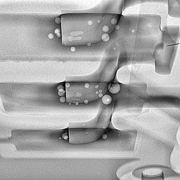
Figure 4. Oblique view x-ray image of gull wing QFP joints where one has a sizeable void located under the heel fillet.
The level of voiding acceptable in such joints does not appear well-defined in common workmanship guidelines. It is left to the assembler and customer to determine what is acceptable. It may be that voiding levels in and around the toe of the joint could be relatively high and still deemed acceptable, yet the presence of much smaller voids located in the heel would be unacceptable and trigger rework.
Use of the void area calculating function, available on many x-ray systems, can give added data to clarify if any voiding, and its position, is in or out of acceptable levels. It should also be considered that even if there is substantial voiding under the heel fillet, is it on a single joint or is it common throughout the whole device? If the former, then perhaps the enhanced risk of failure to that single joint may be small, owing to the quality or solidity of the other joints in the package, making this more of a process issue to note. If the latter, however, then perhaps rework and a more immediate process intervention is warranted?
QFPs may not be as “popular” as they once were, but they should still be checked and not assumed to be fine. Outside of, and to support, optical inspection, check QFPs with x-ray for joint shape inconsistency over the whole device when viewed from the top down. Next, use magnified top-down views to provide improved image detail over similar joints around the package to confirm and highlight any variations. Finally, look at oblique angle views to enhance the analysis.
Note the presence, size and location of any voids. Be prepared to ask difficult questions as to the need to rework the QFP, especially if there is a high level of voiding in many of the joints, or the voids are in the heel fillet region.
Au.: Images courtesy Peter Koch, Yxlon International.
, is an expert in use and analysis of 2-D and 3-D (CT) x-ray inspection techniques for electronics; dbc@bernard.abel.co.uk.


