

Incomplete Crimp Connections
 A lack of compression can be seen nondestructively.
This month we look at crimp connections.
FIGURES 1 and 2 show examples of simple compression connections. Figure 1 shows an excessive length of stripped wire within the crimp termination and a total lack of any compression, which should be easy to see on the wire bundle from the point of entry to the point of compression. Figure 2 lacks compression of the connector, and the stripped wire is barely within the barrel of the connector.
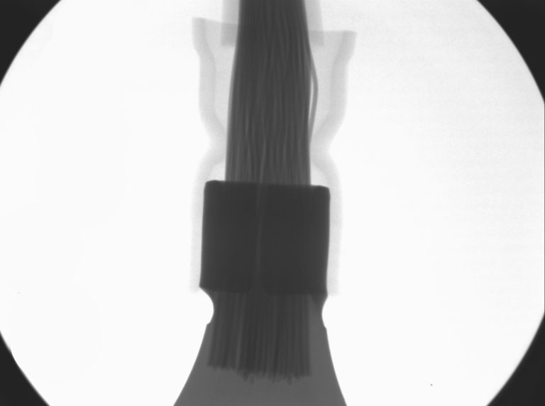
Figure 1. Excessive length of stripped wire within crimp termination and a total lack of compression.
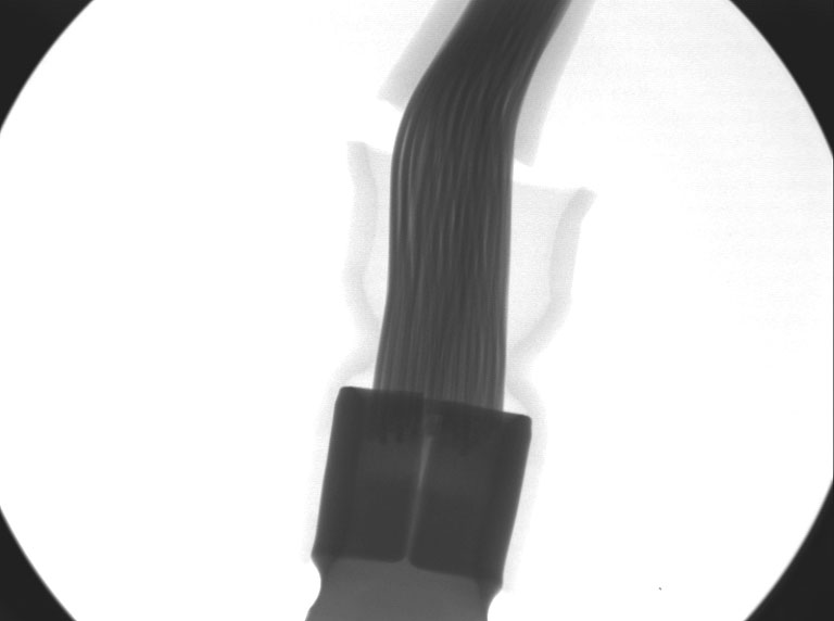
Figure 2. No compression of the connector. Note the stripped wire is barely within the connector barrel.
Obviously the two examples are very simple, but complex multipin crimped or soldered connectors can be examined nondestructively for quality without damage.
Any crimp joint, however simple, should have some form of traceability based on training, operator certification or machine/equipment calibration. Poor design or process control can lead to connection failures, as I have seen many times in my career.
More complex connectors that are sealed can be examined with x-ray. X-ray is a good way of conducting failure analysis or routine audits. It’s also useful for training purposes, where staff can be shown results of wire compression alongside microsections and pull strength measurements.
We have presented live process defect clinics at exhibitions all over the world. Many of our Defect of the Month videos are available online at youtube.com/user/mrbobwillis.
is a process engineering consultant; bob@bobwillis.co.uk. His column appears monthly.


