

0.4mm CSPs and the Automotive Electronics Dilemma

How squeegee technology is driving new high-speed printing solutions.
Recently, our company had some very interesting discussions with a few of the automotive industry’s top electronics manufacturers. Seems that even though there is no space-constrained requirement for automotive device manufacturers to migrate to finer-pitched components, simple supply-and-demand dynamics will dictate their use, like it or not. Because other market sectors are now more widely incorporating 0.4mm CSPs, larger-pitched components are not as readily available for certain applications or, if they are, come at a premium cost.
While the mobile communications sector has been successfully employing 0.4mm CSPs for several years, the majority of these manufacturers are using a 100µm stencil foil for printing the finer pitches. For the automotive industry, where broadband (heterogeneous) assembly is the norm and large connectors have to be printed alongside miniaturized devices, using a 100µm foil isn’t currently an option. The reigning stencil foil thickness for many automotive suppliers is 127µm, so a solution for printing 0.4mm pitches through a 127µm stencil is needed. And, it should also be noted that the customers we spoke with are not necessarily in favor of altering the process, using step stencils or preforms. It was very clear that the preference is to stay with a single thickness stencil so the printing process can be achieved in a single step.
To successfully print 0.4mm CSPs, stencil aperture diameters ranging from 200 to 225µm are required. With 100µm stencils, this puts the area ratio at 0.5 to 0.56µm, which does push the traditional 0.6 rule, but is now generally accepted as manufacturable. However, 220 to 225µm apertures on a 127µm stencil foil yield area ratios of 0.39 to 0.44, which, my friends, is on the proverbial “hairy edge” – if not over the cliff – of standard process capability. To accommodate for the resulting smaller area ratio, some automotive manufacturers enlarge the apertures to diameters of 250 to 300µm, pushing the area ratio to 0.5. To put this in perspective, a 300µm aperture on a 400µm pitch leaves only 50µm on either side of the solder paste deposits. To avoid wet bridging, which is the inevitable result with such tight spacing, these automotive electronics manufacturers were cleaning after every single print. Obviously, this is not a high-volume manufacturing solution. So, step stencils are out; preforms are out; 100µm stencils are out, and larger apertures on 127µm foils are out. What can be done?
We used a 127µm laser-cut stainless steel stencil and tested two aperture sizes: 200µm round apertures (area ratio = 0.39) and 225µm round apertures (area ratio = 0.44). We then evaluated these geometries with a standard metal squeegee print and with energized squeegee technology. The required Cp and Cpk target was 1.33, and therefore, only results that met or exceeded this expectation would be considered. The active squeegee system had produced great results with smaller area ratios on thinner (100µm) stencils, but whether it was scalable to 127µm stencils remained to be seen. Given the tight spacing between deposits, there was near certainty that the standard squeegee process would present difficulties, and that, in fact, was the case. Essentially, it was hit or miss. With a traditional metal squeegee, the 200µm aperture stencil produced a Cp of 1.10 and a Cpk of -0.67, clearly an unacceptable result. When active squeegee technology was employed, the mean material volume (transfer efficiency) improved, but the Cp and Cpk were still unsatisfactory at 0.67 and 0.30, respectively.
Next, the 225µm aperture stencil with a traditional squeegee print was tested and yielded a Cp of 0.67 and a Cpk of 0.30. Though there was definitely a better response than with the 200µm apertures, the results were still outside of the process capability target and inadequate. With the active squeegee, however, the process capability target was exceeded. When the active squeegee technology was employed with the 225µm apertures, a Cp of 2.31 and a Cpk of 1.73 were achieved, which indicates that this solution is very robust and easily incorporated into current automotive electronics printing processes.
The results of this testing are encouraging for several reasons, not the least of which is that active squeegee technology has now been proven to be a scalable approach to managing challenging area ratios without making significant alterations to an established process. And, as anyone familiar with automotive electronics manufacturing will attest, making a process change is no easy exercise. With an active squeegee system, manufacturers can now successfully print 0.4mm CSPs through 127µm stencils using standard aperture geometry of 225µm in high volume. Dilemma solved. We’ll cross the 0.3mm CSP in automotive when we get to it!
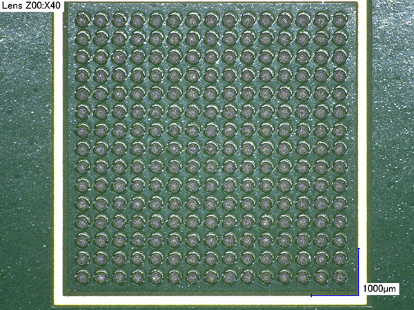
Figure 1. 0.4mm CSP with 225µm apertures, with active squeegee.
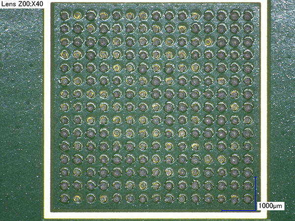
Figure 2. 0.4mm CSP with 225µm apertures, without active squeegee.
Au: A complete paper on this testing and results will be presented at IPC Apex Expo in March 2014.
Clive Ashmore is global applied process engineering manager at DEK International (dek.com); cashmore@dek.com. His column appears bimonthly.


