

For Successful Printing, Don’t Blow the Gasket
 A poor stencil aperture seal may lead to solder bridging.
When we think of a gasket, we often relate it to something experienced in our home, perhaps a plumbing gasket or a gas pipe. A tight seal – or gasket – ensures no leaks. In SMT printing, the same theory applies: A good gasket means no solder paste leaks and a better printing result. With stencil printing, gasketing occurs when the aperture cut into the stencil is pressed firmly against the corresponding pad so it forms a seal. To achieve a good gasket, the aperture should be at least 1:1 with the pad size. If the aperture is larger than the pad, a poor gasket will result. Our company generally advises a one mil (25µm) reduction of aperture size to ensure a tight seal. So, for example, if the pad is 125µm x 125µm, an aperture of 100µm x 100µm is recommended. All things being equal, this approach will help form a good, tight gasket.
Why do we need gasketing? Gasketing is a prerequisite for good printing. When the squeegee blade moves across the stencil, it puts quite a bit of pressure on the paste roll and the tip of the blade, shear-thinning the material and injecting solder paste into the aperture. If the seal between aperture and PCB pad is poor or compromised in some way, solder paste will squeeze out – a leak, in effect – and contaminate the underside (bottom, board side) of the stencil. This, in turn, can cause bridging on the PCB, which is a failure (FIGURES 1 and 2).
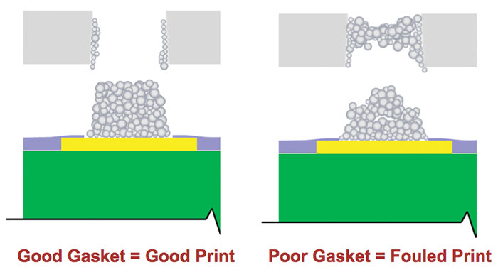
Figure 1. Good stencil versus poor stencil contact and the impact on gasketing.
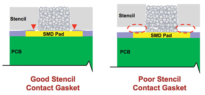
Figure 2. Lack of a proper gasket results in a substandard print.
Considering we now have pitches that are down to 300µm for CSPs and may have gaps between passive components as tight as 100µm in the near future, one can understand the importance of a good gasket. Any contamination could result in material that bridges together instead of forming a nice, singular, well-defined deposit. Even if miniaturization is not part of the program, and perhaps PCBs in your facility are being produced for industrial products or white goods, a poor gasket can still wreak havoc on large pads and forgiving interspaces. When the underside of the stencil becomes contaminated with solder paste material, it can impregnate itself onto the board and create a smudging effect around the pad. If luck is not on your side, this paste will not coalesce into the main deposit during reflow, causing satellite balls to form and become orphaned away from the main deposit, which is also a failure, according to the IPC.
What are the causes of a poor gasket? When the SPI is flagging failures due to bridging, it’s time to investigate the root cause of the issue. If a tight gasket isn’t being formed, there are several potential culprits:
- Machine setup: If the printer and all its modules (board, tooling, stencil) are not planar to each other, then the printing will have gaps. While a gasket may be formed at the point of the squeegee passing over the aperture, that’s just one point of contact. Without all the layers sandwiched tightly together, there will not be a good gasket across the whole of the PCB.
- Gasketing performance also relies on printer cleanliness. We live in a micron world: Verify there is no dried solder paste anywhere inside the machine. A dollop of dried paste that’s 100µm in height when trying to print 200µm on a 100µm foil could break the gasket.
- Tooling: This was the topic of my last column “Tooling May be Out of Sight, but Clues are in Plain View,” August 2018, and its impact cannot be stressed enough. If the tooling height is incorrect, or if something is obstructing the board’s ability to be nested and set into the stencil, a poor gasket will be the outcome.
- Machine capability and alignment of board to stencil: In a perfect world, aperture-to-pad alignment would be 1:1. But, as has been addressed in several previous columns, it’s common for the board not to be manufactured exactly to Gerber. This, as stated previously, is why we recommend cutting apertures slightly smaller than the pad. However, the machine has to be able to achieve repeatable alignment; a system with less than 20µm in accuracy at a minimum is required to have the capability to manage today’s technology effectively. For ultra-fine-pitch work, the machine accuracy should be between 10µm to 12µm.
Seal the deal. When inspection data indicate a problem, start looking for the cause. While some manufacturers might throw in an extra clean to remove any underside stencil contamination, that’s not the advisable remedy and is likely only treating the symptom, not the disease. Several vital signs could provide clues to the cause of any gasketing issue; do the investigative work and fix the problem.
is global applied process engineering manager at ASM Assembly Systems, Printing Solutions Division (asmpt.com);
clive.ashmore@asmpt.com. His column appears bimonthly.


Press Releases
- Altus Adds LPKF CuttingMaster 3290 to Depaneling Portfolio
- Kurtz Ersa Partners with E-tronix for Sales in Illinois and Wisconsin
- XLR8 EMS Welcomes Raul Jorge Lopez Jr. as Director of Program Management and Procurement
- Koh Young America Promotes Ramiro Mora to Lead Service and Applications in Mexico and South America