Corrosion Analysis
Halides present post-reflow can cause severe corrosion.
Several board assemblies had failed in the field and exhibited areas of corrosion in close proximity to assembled components. The most common source of corrosion on electronic assemblies is residual flux. Fluxes are specific chemistries applied during soldering that improve wetting of the solder to the pad and component when forming the solder joint. They can be highly reactive chemicals that, if left on the assemblies, can lead to corrosion, electrical degradation and decreased reliability. In the presence of moisture and electrical bias, flux residue can enable dendritic growth as a result of electrochemical migration (ECM).
To establish the source of the corrosion products, the technical data sheets and materials safety data sheets (MSDS) can be used to help evaluate the chemistries of the approved fluxes. The cleaning process is also evaluated to ensure the efficacy of cleaning the fluxes used in the manufacturing process. Furthermore, by establishing a correlation between the composition of the residues and the flux chemistries, one can eliminate or confirm the source of the corrosion. Analysis of the residues may be accomplished by employing scanning electron microscopy with energy dispersive x-ray spectroscopy (SEM/EDS).
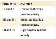
The introduction of chemistries promoting the advancement of corrosion in electronic assemblies may appear paradoxical. However, with the selection of a proper flux and effective cleaning processes, any impact upon performance and long-term reliability can be effectively negated. An abundance of flux types are currently available. J-STD-004B characterizes flux by type: rosin (RO), resin (RE), organic (OR) and inorganic (IN), which are described further in the standard. Flux activity is also designated by the degree of its ionic and corrosive actions (TABLE 1). Flux types are identified using a 0 or 1 to indicate the absence or presence of halides. A halide-free flux providing adequate soldering performance with low residue levels may appear ideal. However, flux selection may rely on board type, material compatibility, standard specifications, component mounts and solderability. IPC-CH-65A,“Standards and Guidelines for Cleaning of Printed Boards and Assemblies,” states, “Cleaning operations after soldering should be chosen on the basis of degree of cleanliness required, type of flux residue to be removed, and accessibility of this residue to cleaning solvents.”
Table 1. Flux Designators
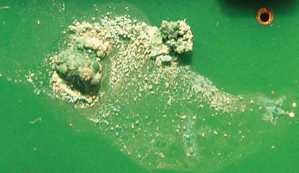
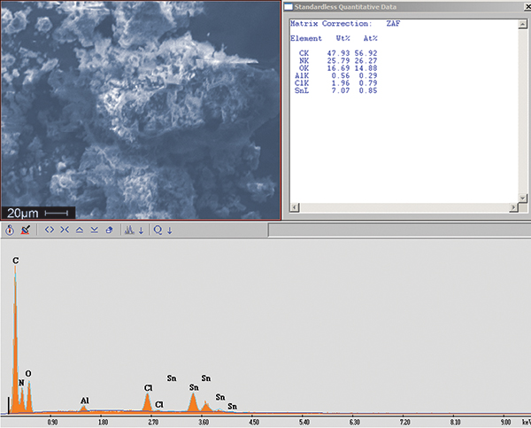
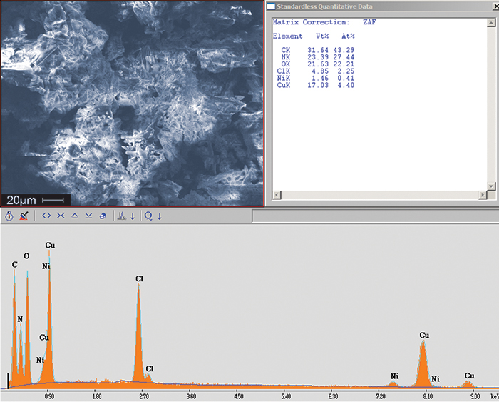
Optical microscopy was used to obtain images of the white residue (FIGURE 1) and green residue (FIGURE 2) observed on the assembly and its components. SEM/EDS can provide a qualitative representation of these residues using high magnification microscopy in conjunction with EDS for quantitative purposes. Analysis revealed the white areas of corrosion to be consistent with tin chloride residue (FIGURE 3) and the green areas to be consistent with copper chloride residue (FIGURE 4). These residues may form when copper and tin react with chloride ions, which likely came from an aggressive flux that had an extended exposure time on the assembly. Carbon, nitrogen, and oxygen also were present in both residues and are typical organic components of the flux. A review of the technical data sheets for the flux materials used in the manufacturing process referenced use of L0 materials. L0 materials are halide-free and were neither the source of the chlorides nor the cause of the residue. Further review of the materials revealed an aggressive flux was used in the selective soldering process. The designator ORH1 indicates the highest flux activity level in the OR category and halide concentrations greater than 2%. It is likely this flux is the source of the chlorides and the cause of the residue.

Figure 1. Optical micrograph of white residue residing on components.

Figure 2. Optical micrograph of green residue residing on board assembly.

Figure 3. SEM image of white residue removed from assemblies. EDS confirmed the presence of tin and chlorine, suggesting a tin chloride residue. The carbon, nitrogen and oxygen are typical for organic components in flux.

Figure 4. SEM image of green residue removed from the assembly. EDS confirmed the presence of copper and chlorine, suggesting a copper chloride residue.
Chloride remaining on the assemblies after exposure to H1 fluxes is common. When combined with moisture and electrical bias, the presence of these chlorides is instrumental in corrosion. An assembly properly cleaned and rinsed after reflow can effectively eliminate the remaining halide fluxes, removing any ionic species necessary for corrosion. Manufacturing processes must also be thoroughly reviewed. This ensures non-approved materials, which may lead to reliability issues such as the corrosion residues observed on these assemblies, are not applied.
(aciusa.org) is a scientific research corporation dedicated to the advancement of electronics manufacturing processes and materials for the US Department of Defense and industry. ACI offers analytical services, component engineering and design services. For information and assistance with designing experiments to verify the integrity of electronic assemblies for military applications, contact the Helpline at 610-362-1320; helpline@aciusa.org.


