Life After SAC 305
 With RoHS exemptions set to expire, can SAC 305 hang on?
It is not the strongest of the species that survive, nor the most intelligent, but the one most responsive to change.
– Leon Megginson
The final steps of RoHS will be phased in over the next 24 months. Once implemented, lead will be virtually eliminated from solder in the electronics assembly supply chain. With the last exemptions applying predominantly to high-reliability applications, materials in use are being scrutinized to determine if they can perform to the mission requirements of high-reliability PCBs.
Concurrent to this material concern is the unrelenting trend in microelectronics: more functionality and performance in smaller spaces. As circuitry becomes denser and more power is inserted into smaller spaces, an inevitable byproduct is heat. These two realities, high-reliability requirements and increased power density, are exposing deficiencies in the de facto lead-free solder alloy, SAC 305. SAC 305 has performed adequately to this point. The processing temperatures are acceptable. It has proved sufficiently durable and is largely compatible with other common materials, albeit at considerably higher cost than the SnPb it replaced. Typically, if an alloy other than SAC is in use, it’s for cost containment rather than solder joint reliability characteristics. But the needs of the industry are evolving based on the aforementioned changes in regulation and reliability requirements. As a result, SAC 305 may fall out of favor, as it has a variety of undesirable inherent characteristics.
First and most concerning to several high-reliability users (including LED and automotive in particular) is the degradation of the mechanical properties of SAC 305 when exposed to elevated temperatures that can lead to solder joint failure. FIGURE 1 demonstrates SAC 305’s resistance to deformation under increasing tensile (pull) stress. The black line shows the alloy in the “as-cast” state, where it was tested immediately following casting. The blue line is the same test performed after the alloy sample is exposed to 150°C for 18 hr. As the graph demonstrates, SAC 305’s resistance to deformation drops in half with exposure to elevated temperatures.
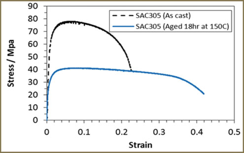
Figure 1. Increasing tensile strain.
FIGURE 2 is another measure of degradation of the mechanical performance of SAC alloy, but rather than showing degradation under increasing force, the alloy degrades under constant force over time. In this case, the “as-cast” SAC 305’s resistance remains consistent where the “aged” sample experiences a complete loss of strength in a comparatively short period of time.
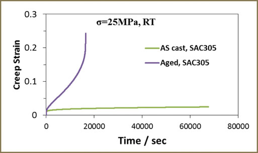
Figure 2. Tensile strain over time.
In FIGURE 3, the bar graph shows the “aged” sample with a 20% drop in hardness when tested with a Vickers hardness tester. These tests clearly demonstrate the loss of performance of SAC 305 when exposed to high temperature.
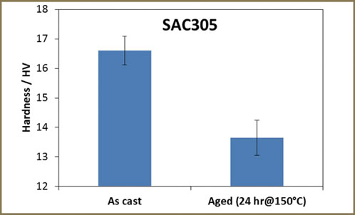
Figure 3. Alloy hardness test.
The loss of strength and durability of the alloy exposed to high temperature is due to a change in the microstructure of the alloy’s crystalline structure. FIGURE 4 compares micrographs of SAC 305 alloy before and after aging. The change in the alloy’s microstructure is profound and easily observed. The dark areas in the image are coarsened precipitate of SnAg intermetallic compounds that leads to the weakening of the alloy. New alloys have been developed using a variety of elements and micro-alloys, which minimize this phenomena and create an alloy with superior thermal fatigue resistance and mechanical strength.
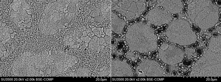
Figure 4. Micrographs of SAC 305 alloy before (left) and after aging 24 hr. at 150°C.
It is understood among the handheld device community that SAC 305 drop shock performance is a reliability concern. SAC alloys containing 3% or more silver are considered “high silver” and exhibit a condition referred to as silver “platelet” formation. The solidification properties of SAC alloys are inconsistent, and this permits development of SnAg intermetallic structures that have different physical and mechanical properties than the surrounding alloy. FIGURE 5 is an interesting focused ion beam image. It shows these platelets in three dimensions and how drop shock cracks can propagate along the interface between a platelet and the bulk alloy.
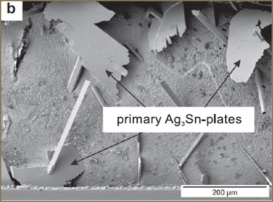
Figure 5. >3% silver SAC alloys exhibit poor drop shock performance.
The simplest remedy to this condition is to reduce the silver content of the alloy, thus reducing SnAg intermetallic. It is common to find BGAs in devices subjected to drop shock to be assembled using spheres composed of a low-Ag SAC alloy to improve performance. Reducing the silver content in the solder alloy for assembly is more complicated, however, as doing so increases the alloy’s melting point and reduces wetting performance.
Tin whiskering is a particular concern for high-reliability electronics. Tin whiskers are a stress-relieving phenomenon that high-Sn alloys can exhibit over extended periods of time. These are “micro-extrusions” of tin (FIGURE 6) that emanate from the surface of the solder and can result in an electrical short. The only mitigation strategy available today is conformal coating, and this does not prevent development of the whiskers but is merely a “catch and contain” strategy. While it is possible for tin whiskers to form in solder joints, they are much more likely to emanate from electroplated pure tin due to the atomic structure of the tin plating.
New options and understandings are emerging to meet the demands of multiple markets as RoHS exemptions expire. As discussed in our March 2017 column, we can expect applications will emerge where SAC 305 is displaced by “designer” alloys. These new alloys will provide developers and assemblers with new tools to meet the evolving demands of the electronics market. It is even feasible SAC 305 will be dislodged by a new de facto alloy that better serves the needs of the market.
To improve is to change; to be perfect is to change often. – Winston Churchill
is technical marketing manager at AIM Solder (aimsolder.com); toneill@aimsolder.com.


