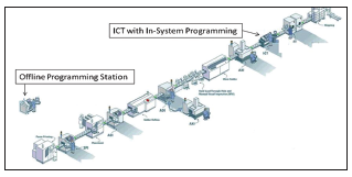
The decision rests on the line beat rate versus ICT test cycle time.
Modern electronics – cellphones, TV set-top boxes, laptops – contain at least one programmable device on board that usually contains boot-up or self-test firmware to enable these products to perform their functions properly. In general, there are two methods by which these devices are programmed: offline or in-system.
How does one decide on offline programming or ISP? One key consideration is the cost of each method. Let us look at pros and cons of these two methods that contribute to the overall costing.
First, let’s define each of these methods:
- Offline programming. Device programming carried out independently of the actual production line before device is attached to the printed circuit board.
- ISP. Device programming carried out in the actual production line; device is installed on the assembly before programming is performed.
The sole benefit of programming offline versus in-system is that it takes out that time from the overall ICT test cycle time equation. If the SMT line beat rate is much faster than the overall ICT test cycle time, the ICT station will be a bottleneck for the production line. Removing the programming portion from the ICT stage will improve the overall efficiency of the production line. The programming time depends on many factors, like the size of the data to be programmed, programmer clock speed, number of devices to be programmed, whether the program is implemented directly onto the device or via an upstream boundary scan JTAG port to program device, etc.
On the other side of the coin, offline programming does have some big challenges. The first is inventory control. There will be multiple firmware versions across the customers’ range of products, and there will be even cases of multiple firmware versions for a single product with different functions turned on for different market needs. Having offline programming for all these devices will require a good inventory control process. Imagine loading the wrong preprogrammed devices onto boards: the effort and cost of replacement would be tremendous.
The second challenge with offline programming is the inability to reprogram the device post-soldering. Often, firmware versions are frequently changed, especially during NPI. New firmware may be released during the production build, and the inability to reprogram the device online means one has to replace the device manually. Or, if boards have been returned from repair, functional test or outside the factory, there usually are slight changes to the firmware, and the boards must be reprogrammed in the ICT. This reinforces that the ability to program in the ICT station is critical in a production environment.
An offline programming station requires additional resources: operators, real estate, and of course the programming station itself. On the other hand, implementing ISP may require additional hardware or software on top of the existing ICT, not to mention development of the ISP solution.
Simultaneous Programming
Performing programming on two similar boards simultaneously achieves two boards within one test cycle time. It can also mean programming two or more devices within the same board simultaneously, circuit topology permitting. How fast can ISP be? Consider real-time data I collected from two recent ISP projects. In both cases, the ICT was an Agilent Medalist i3070 Series 5 with plug-in cards.
Project #1:
Product: Smart meter
Fixture: One-up (single board)
Programming three different devices on board: M24512 (EEPROM), M25P10 (SPI flash), STM32F101 (MCU)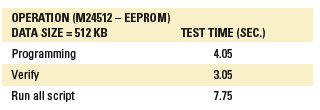
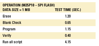
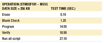
Project #2:
Product: TV setup box
Fixture: Two-up with throughput mode
Programming AT26DF081A (flash) on board.
Note that for this project, programming was performed on two boards simultaneously. The test time shown below is actually for two boards. The programming time for one flash device by the EMS company’s offline programming station took 35 sec., which was significantly slower than the ISP programming time in the table below.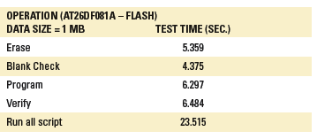
Design for programmability. When adapting ISP, other than the program time incurred in the total test cycle time, one should consider design for programmability. Simply put, there must be test access to the data, clock and control signal lines of the programmable device. In most cases, there usually is a processor or controller that accesses the firmware from these downstream programmable devices. One must also consider the means for disabling these upstream devices to the programmable devices. There must be ways to disable the upstream devices properly in order for the programming to perform successfully. If upstream devices are not properly disabled, there will be interference, and programming success will be intermittent, if at all.
In conclusion, there is no absolute answer to whether to adopt offline programming or ISP. One has to decide, based on the factors above, the method that best suits the products and the production environment. Both methods complement each other.
My opinion is that ISP capability has to be implemented for every product with devices that require programming. Whether an offline programming station should be added depends on the SMT line beat rate versus the ICT test cycle time. ISP is an available and viable option to address the gaps in offline programming. It can double up as a check point to verify the data content pre-programmed by the offline programming station. Where necessary, more ICT machines with ISP can be added to match the SMT line beat rate.
Tan Beng Chye is a technical marketing engineer at Agilent Technologies (agilent.com); beng-chye_tan@agilent.com.
Any metal that comes into contact with the electrolyte could corrode.
Several types of corrosion commonly occur – and in several ways.
A critical factor in preventing corrosion in electronics is maintaining the state of cleanliness. This is not easy. Corrosion is defined as the deterioration of a material or its properties due to a reaction of that material with its chemical environment.1 So, to prevent corrosion from occurring, either the material or the chemical environment must be adjusted. Adjusting the material usually means replacing it with a less reactive material or applying a protective coating. Adjusting the chemical environment usually means removing ionic species through cleaning, and removing moisture, usually with a conformal coating or hermetic package. Ionic species and moisture are problematic because they form an electrolyte able to conduct ions and electricity. Any metal that comes into contact with the electrolyte can begin to corrode.
Several types of corrosion can commonly occur on electronics assemblies.
Gas phase corrosion. Some metals used in electronics, such as copper, nickel and silver, are susceptible to gas phase corrosion. In the cases of copper and nickel, the metals react with oxygen in the air to form a thin oxide layer and an unsolderable surface. This is why surface finishes are used. They serve as protective coatings by preventing copper from oxidizing and retaining a solderable pad on a bare board. One such surface finish, immersion silver, protects the underlying copper, but the silver itself is susceptible to attack from sulfur-containing materials and gases in the atmosphere, leading to tarnish (Figure 1). Prevention of exposure to sources of sulfur is key to preventing tarnish from occurring. Sulfur is found in air pollution, rubber bands, latex gloves, desiccant, and sulfur bearing paper used to separate parts.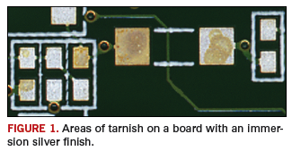
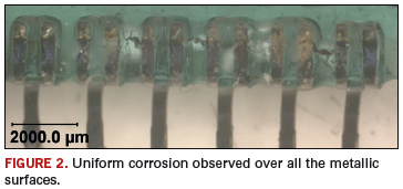
Uniform corrosion. Uniform corrosion is evenly distributed across the surface with the rate of corrosion being the same over the entire surface (Figure 2). One way to determine the severity of the corrosion is to measure the thickness or penetration of the corrosion product. Uniform corrosion is dependent on the material’s composition and its environment. The result is a thinning of the material until failure occurs.2 Uniform corrosion can be mitigated by removing or preventing ionic residues and preventing moisture.
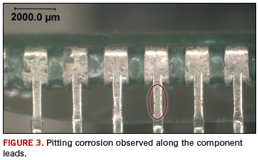
Pitting corrosion. Pitting corrosion is a localized form of corrosion where the bulk material may remain passive, but pits or holes in the metal surface suffer localized and rapid surface degradation (Figure 3). Chloride ions are notorious for forming pitting corrosion, and once a pit is formed, the environmental attack is autocatalytic, meaning the reaction product is itself the catalyst for the reaction.3 Pitting corrosion can be mitigated by removing or preventing ionic residues and preventing moisture.
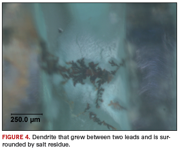
Electrolytic metal migration. In the presence of moisture and an electric field, electrolytic metal migration occurs when metal ions migrate to a cathodically (negatively) charged surface and form dendrites. The dendrites grow and eventually bridge the gap and create an electrical short. Materials susceptible to metal migration are gold, silver, copper, palladium and lead. These metals have stable ions in aqueous solution that are able to travel from the positive electrode (anode) and deposit on the oppositely charged negative electrode (cathode). Less stable ions, such as those of aluminum, form hydroxides or hydroxyl chlorides in the presence of high humidity and chlorides. An example of a copper dendrite is shown in Figure 4. Electrolytic metal migration can be mitigated by removing or preventing ionic residues and moisture.
Galvanic corrosion. Galvanic corrosion occurs when two dissimilar metals come in contact with one another or are connected through a conductive medium such as an electrolyte. A soldered joint is a composite system where many different materials are connected. Within the joint or between joints and other conductive circuitry, DC circuits can be established that will corrode the most anodic material.4 When ionic species are present, such as flux residues and moisture, an electrolyte can form. The corrosion at the metal forming the anode will accelerate, while the corrosion at the cathode will slow down or stop. In a poorly deposited ENIG surface finish, a porous immersion gold layer exposes the underlying electroless nickel. The large difference in electrochemical potential between the nickel and gold causes corrosion of the nickel layer, while the gold acts as a powerful cathode. As corrosion proceeds, pitting of the nickel can extend into the underlying copper and cause further corrosion. If there is no porosity in the gold layer, but instead, a gap between the metallic component and the resist edge, the metallic layers can be exposed to solution allowing galvanic corrosion.5
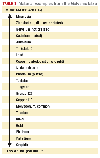
Table 1 lists metals in order of their relative activity in sea water (the Galvanic Table from MIL-STD-889, Dissimilar Metals). Generally, the closer the metals are to one another in the listing, the more compatible. However, in any combination of dissimilar metals, the more anodic metal will preferentially corrode. To prevent galvanic corrosion, careful selection of adjacent materials must occur in the design phase. To mitigate galvanic corrosion from occurring in the field, an electrolyte must be prevented from depositing on any connection of dissimilar metals.
Corrosion can be mitigated by preventing electrolytes from forming. This is accomplished by ensuring that any ionic residues are removed after component handling, bare board fabrication, and assembly, as well as preventing salts from depositing on the assembly from extreme environmental conditions. Moisture can be prevented by using a conformal coating or hermetic package. Also, materials selection in the design phase is important so that metals with dissimilar electrochemical potentials are not directly connected. If dissimilar metals must be used, such as when using specific surface finishes, like ENIG, then ensuring good bare board construction is a critical step in reliable, corrosion-free electronics.
References
1. Bob Stump, National Defense Authorization Act for Fiscal Year 2003. Pub. L.107-314. 2. Stat. 116.2658, December 2002.
2. B. D. Craig, R. A. Lane and D. H. Rose, “Corrosion Prevention and Control: A Program Management Guide for Selecting Materials,” AMMTIAC, 2006: 61.
3. Electronic Device Failure Analysis Society, Microelectronics Failure Analysis: Desk Reference, ASM International, 2004: 3.2.
4. Perry L. Martin, Electronic Failure Analysis Handbook, McGraw-Hill, 1999: 13.42.
5. Rajan Ambat, “A Review of Corrosion and Environmental Effects on Electronics,” 2006.
ACI Technologies Inc. (aciusa.org) is the National Center of Excellence in Electronics Manufacturing, specializing in manufacturing services, IPC standards and manufacturing training, failure analysis and other analytical services. This column appears monthly.
Avoid molten solder on the pad, which could minimize pad material dissolution.
Large, high-mass assemblies are a challenge for any soldering process, but are particularly troublesome for selective soldering, where process heat is applied only to the bottom side of the assembly. Such boards require continuous, real-time topside preheating during the selective soldering process.
For this reason, we often find selective soldering machines equipped with a preheating module that applies heat to the top side of the PCB during soldering. For high-mass assemblies, topside preheating promotes the draw of the solder through the barrel to the top side of the board, enhancing solder fillet formation. The implementation of internal continuous preheat during selective soldering improves thermal distribution and solderability of difficult assemblies.
This type of topside preheating configuration is not practical or possible on machines that grip and robotically move the PCB, since the preheater would need to travel with the board, and the gripper simply is in the way. A topside heating module can be used as the primary preheating function, or to maximize productivity when used in combination with optional discrete preheaters to maintain board temperature during soldering. Some systems are equipped with an optical pyrometer that reads the actual PCB temperature during the process and provides closed-loop control. The importance of proper closed-loop preheater control based on PCB temperature cannot be overemphasized.
Our selective soldering systems typically run solder temperature in the 300°-325°C range. It is important to remember we are replacing/emulating hand soldering, where the soldering iron tip temperature is around 375°C. We are not reproducing wave soldering. Molten solder has significant thermal capacity and heats the solder site much more rapidly than the conventional iron, overcoming most of the difficulties soldering heavy pins. However, on thermally demanding sites or thick multilayer boards, preheating contributes significantly to the outcome quality and provides two distinct advantages. First, the process is expedited significantly, depending on the thermal mass the wave would need to heat. Second, the molten solder does not need to dwell on the pad any longer than necessary, thereby minimizing dissolution of the pad base metal. (This can be a big problem with Pb-free alloys due to the aggressive behavior of molten tin.)
Another option is the use of both standalone and inline preheaters for high production systems. These units raise board temperature while the previously heated board is being fluxed and soldered in the selective machine. However, on extremely demanding boards (e.g., backplanes) with many sites to be soldered (and with a long soldering process time, such as 5 min. or more), the board may partially cool, causing a gradual change in the process, and thus negatively affecting solder joint quality. Therefore, for maximum productivity when processing such boards, use of both inline and on-board preheaters (in concert) is recommended.
Mention preheating, and most people envision a flat panel or array of lamps, but selective soldering machines can focus and control superheated nitrogen delivery to a very small, user-defined area of an assembly (Figure 1). This preheater type is appropriate for soldering operations where large area bottom-side or topside preheating are not feasible, and in situations where extended preheat cycles or solder dwell times represent a danger to the subject component or adjacent components.
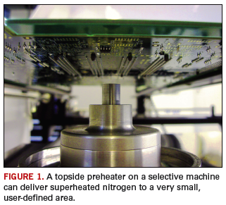
We find this is a good method to proportionately control a number of critical parameters, including ramp-to-temperature, volume of flow, and dwell time, creating a true small-area pre-heat profile. Used in conjunction with a machine’s nozzle and nitrogen cap design, the user in many cases can program the delivery of the right amount of nitrogen, with the proper profile, through the solder nozzle before the solder can begin to flow, effectively preheating and preparing the soldering site with the protection of nitrogen, which is usually at the solder liquidus temperature, without any oxidation or degradation. It’s just another effective tool in the selective soldering user’s arsenal.
Alan Cable is president of A.C.E. Production Technologies (ace-protech.com); acable@ace-protech.com.

First of a two-part look at ways to keep print operations running smoothly.
With all the advances in screen printing technology – from cycle times to accuracy to inspection capability – it’s sometimes easy to forget that, just like your own health, keeping your process in check requires periodic preventative maintenance. So, in this column and the next, I’ll discuss the three areas central to a healthy print process, along with simple remedies for certain problems. They are:
- Correct volume.
- Correct location.
- Timeliness and repeatability.
First, let’s talk about material volume – either too little or too much solder paste. For insufficients (too little paste), I generally analyze four things: volume of paste in front of the blade, material compatibility with the process, squeegee type/squeegee angle and the stencil.
Paste volume in front of the squeegee blade. Remarkably, this is a common issue, but is easily resolved. The rule of thumb is that there should be a 15 mm (about 0.75˝) diameter roll in front of the blade. While this seems easy to monitor, in busy factories, it is often overlooked, but can be remedied through use of automatic paste height monitors.
Material compatibility with the process. Many firms have taken on miniaturization from a manufacturing point of view, but not necessarily followed suit with their materials. For smaller ranges of apertures (sub 200 µm), a Type 4 or even Type 5 solder paste may be required. In general, at least four to five solder particles should fit across the width of the smallest aperture. If aperture width has been reduced, but solder paste type not adjusted, insufficients may result because of blocked apertures. Also consider material age. If a product has been running fine and then all of a sudden insufficients begin to appear, it could be a material drying issue. Even a slight change in the material will impact the print, especially when running a process with incredibly small apertures.
Stencil considerations. Of course, stencil integrity and cleanliness also factor greatly in proper paste volumes. Improper cleaning can render an aperture area ratio significantly reduced from the ideal of 0.66. If the stencil has been designed improperly, without regard to area ratio rules, or if it isn’t manufactured with properly calibrated lasers or a process that ensures debris-free aperture walls, then insufficient volumes could result.
Squeegee type and angle. Squeegee angle is incredibly important, and slight adjustments can have a huge impact on aperture fill. Plus, it’s not just the manufacturer-recommended angle to be concerned with: Pressure also must be evaluated. If you’re putting a tremendous amount of pressure on the squeegee, the bend will affect the angle and, therefore, the print. Proper maintenance also is key. Just because squeegees are metal doesn’t mean they are indestructible. Warped squeegees and worn tips can wreak havoc on prints. All it takes is a few seconds at the end of each shift to look down the length of the blade for damage. If there is, the blade should go in the bin.
Conversely, too much solder paste can result in bridging or stringing, and certain inputs should be evaluated to reveal the source. Similar to problems that occur with too little paste, factors that should be analyzed in relation to excessive volume include materials, squeegee, stencils and tooling support.
Material. If the viscosity of the solder paste isn’t right, then slumping, bridging and stringing can occur. Aside from the obvious formulation issues, viscosity also can be impacted by environmental conditions (high humidity, for example) and cleaning solvents on the stencil. All of these potential viscosity challengers should be evaluated.
Squeegee. Again, the angle is essential for ensuring the proper amount of solder paste in the apertures. An angle that is too shallow (45° and below) may create a volume that is too high. But, as noted, blade pressure also can impact volume. A 60° blade, under excessive pressure, could cause material volume to be overshot.
Stencils. Precise fabrication of the stencil is critical. Apertures that are too large – even slightly – can release too much paste volume, leading to bridging. Cleanliness also has an impact. If a smear is left on the stencil, the extra thickness might cause too much material volume to be pulled when it is released from the aperture.
Tooling supports. All tooling needs to be clean, flat and maintained. You’d be amazed at how many tooling supports are covered in dried solder paste, which, once set, is much like cement. With too much dried paste on the tooling block, the board often doesn’t gasket well to the stencil; these gaps will lead to extra material volume.
Monitoring these “gotchas” on a regular basis will most certainly lead to a healthier print process. In my next column, we’ll continue this discussion with a look at location/accuracy and repeatability. Until then, keep an eye on those paste volumes!
Clive Ashmore is global applied process engineering manager at DEK International (dek.com); cashmore@dek.com. His column appears bimonthly.
Mid-tier EMS provider Mack Technologies uses a data-driven approach to satisfy customers.
For two years running, Mack Technologies has taken home top honors in Circuits Assembly’s Service Excellence Awards for companies of $100 million to $500 million in annual revenues. What’s its secret?
A customer service strategy based on execution performance and using data, derived through open and honest communication with customers, to drive improvements in performance, company officials say. Westford, MA-based Mack (macktech.com) attributes its ability to follow this strategy to an evolving corporate culture that places a high value on supporting customer requests and exceeding expectations.
In an interview with Circuits Assembly, president John Kovach and vice president of sales and marketing Will Kendall described Mack as a fairly conservative company, one that chooses its customers as much as it is chosen by them. Mack, they said, pays close attention to its customers’ financial stability and engineering needs, and once engaged, spends countless hours assessing their customers’ needs and Mack’s performance in meeting those needs. Excerpts:
CA: Describe Mack’s quality system.
JK: Employee performance is evaluated based in part on customer quality scorecards. We do the same things the same ways in all three sites. Profit sharing is tied to company profitability and customer satisfaction. The scorecard looks at five to six aspects with detailed subheadings. We ask for comments and feedback for any score that’s not best in class. Program managers and executive sponsor (VP, GM, president) for most accounts.
We meet as frequently with customers as we can, and go through scorecarding with them. Ownership fosters long-term relationships. Mack strives for long-term partnerships, and we avoid doing anything for short-term financial gain that might negatively affect a long-term customer relationship.
CA: What are the metrics you use?
WK: On the tactical side, customer metrics focus on execution, like on-time delivery; return material authorization (RMA) turnaround; quality – yield at customer site, returns, internal DPMO; availability of quality info, such as frequency and accuracy; flexibility – we let the customer dictate that; for every customer it’s different. We define flexibility as “changes to the steady state of business.”
We design a supply chain to fit the customers’ inventory management and needs.
Moreover, compensation has been tied to profits and customer satisfaction since the inception of Mack Technologies. If you concentrate on something long enough, it becomes part of the culture. It’s part of the belief system of the team.
CA: Is the scorecard-related compensation substantial?
WK: The maximum payout can be a significant portion of an employee’s compensation. The formula was developed about 25 years ago, and the axes sometimes change, but the internal payout rates have been consistent.
CA: Does Mack approach its suppliers with the same level of detail?
WK: Our supply base is a major factor in our performance for our customers.
JK: We’re demanding but fair, and view (the supply base) as a long-term extension of our own capabilities.
CA: Are the metrics qualitative or quantitative?
WK: Some of the qualitative things include asking customers to rank us against our competitors. This is a major factor in our analysis. We ask if their view of us is favorable or not.
Quantitative metrics are rolled up and put into an algorithm, and weighted with qualitative metrics. It’s a homegrown formula that has existed for quite awhile. We also push for the qualitative aspects. The typical scale is 1 to 5. (For the internal scale, it’s 0 to 100). The score goal is aggressive and consistent year-to-year.
CA: One of the problems in a long-term customer relationship is that mistakes are bound to happen. How do you avoid those mistakes from building up to the point where, in the customer’s eyes, you have become an inferior supplier?
WK: What separates companies in terms of customer perception is how you react to mistakes to ensure the same mistake never happens again. Are you implementing procedures to minimize the impact and ensure they don’t happen again?
JK: I think quality reviews help keep that on balance. If you continue to meet with their senior executives and objectively review performance data, you establish credibility and can view the overall performance in context of the whole relationship, as opposed to a specific instance that may be more emotionally memorable, but overall insignificant in the greater scope of the relationship. At the end of the day, what matters most is our longstanding execution and performance for our customers.
WK: With quality business reviews, it helps both companies look at all the data for a given period, instead of just the performance for the immediate short-term period leading up to the review.
CA: How do you ensure the Mack approach can withstand the loss of key personnel?
JK: The systems are well-designed, so that if we lost key members of the staff, the system would survive. Then it’s a level of discipline. All three sites [Ed.: Mack has facilities in Massachusetts, Florida and Mexico] meet one to two times each week. There are monthly performance data meetings. The system is simple to understand. Sales and operations talk across all three sites.
CA: How do you ensure the Mack culture during the hiring process?
JK: Internal management has been in place for a long time, so there’s mentoring. We try to vet the employee recruiting process, so we can find the right people for the task. We look at their background. Mentioning only “profit” without also mentioning customer satisfaction and service is a red flag. We look for candidates who talk about the customer.
CA: Besides the program managers, who within Mack is allowed to engage with the customers?
JK: Quality, Materials, Test, Finance and Operations. The majority of people with access to communications are allowed and encouraged to talk with customers. The program manager is always involved in the communication too.
Meetings are generally by phone or onsite, depending on the customer location. We like to see the customers in person when it makes sense.
CA: Say you attained the corporate goal in a given year. Now what do you do?
JK: We don’t stop once we achieve the goal. When your performance is good, you are establishing credibility. Over time, we strive to further enhance our performance – even when we have set a high watermark for expectations from our customers. If you are missing 20% of your metrics underperforming, the relationship isn’t going to go anywhere.
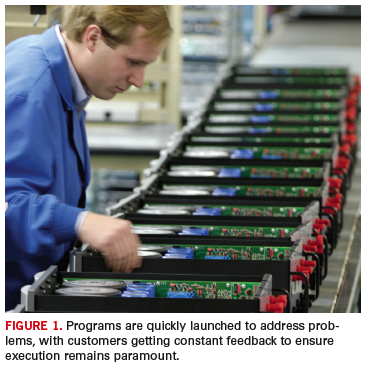
WK: Customers tell us when they think we aren’t performing. This openness and honest communication really only works when the customers feel comfortable that they can tell us where we can improve and that we will constructively receive the feedback. We have a flat management team. There are not many people our customers have to call in order to get an answer. Information usually can be transferred quickly because we are flat. Our structure enables a level of communication that some others might not have.
JK: I think your reputation becomes critical in the sales cycle.
CA: What is the program manager’s role in all this?
WK: The manager is responsible for ensuring staff is following through. It comes from the top and flows to the whole team. All feedback is shared with teams, so there’s a lot of formal feedback.
JK: We use the same scorecard across the company, so when we hire a PM, it’s a critical part of their training. And we launch programs to address problems and bad trends, e.g., RMA.
‘Flexible, But Diligent’
"A good, seasoned team of professionals that offers a lot of industry knowledge when you need it."
That’s how customers see Mack Technologies. As part of this reporting, Circuits Assembly spoke with a pair of Mack customers: Thomas Kokernak, director of global supply chain management at Kopin Corp. (kopin.com), an OEM of ultra-small LCDs and heterojunction bipolar transistors for consumer, industrial and military applications, and a Mack customer for almost three years; and Glenn Cozzens, vice president of engineering, operations, and information technology at ThingMagic (thingmagic.com), a developer of RFID technology. (Cozzens has outsourced to Mack at multiple employers.)
CA: What services does Mack provide you?
GC: Printed circuit board and box-builds. Mack does the parts procurement through functional test. What we call a box-build is really a small reader, like a router. These are RF devices. Mack also manages the material required from other suppliers.
TK: Mostly manufacturing, but when needed they can perform environmental test and can support various other things such as manufacturing solutions for coatings and boards. They also offer us higher-level manufacturing services like component procurement. We are leveraging some of [Mack’s] Florida asset capability for some of our customers. From quality perspective, they are serving us in both locations, as some of our customers are near their Florida site. The other thing I like is the parent company [Mack Group] has molding capability, so if I wanted to bring them a box-build program, they span the network of what I would need done. And they have prototyping capability.
Why do they make us happy? The quality is good, even first time out the door. Mack is very flexible and very responsive, but diligent in making sure documentation is in place.
CA: How do you typically communicate with them?
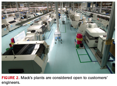
GC: We do a hybrid. As head of engineering and operations, I talk to Will Kendall. Our test engineer talks to their test engineer. Our process engineer talks directly to their process engineers and program manager. We go there regularly and have weekly meetings. We use email, phone, text and electronic transfer of data.
TK: Through the program manager, or engineers talk to engineers. The relationship is such that it’s not unusual for our engineers to say they are going to talk to Mack’s.
CA: How have you handled quality issues?
GC: When we run into a manufacturing defect – and everyone has them – we formally request a corrective action. First, we want to see a containment measure, in order to prevent more failures from making it out. Then we work on root cause. Of all the CMs I’ve worked with, they are the best at diagnosing failures on the line. Sometimes the corrective action is on their side, like a process change or a footprint change; sometimes our tester didn’t find something that needs to be corrected.
TK: If there is a quality issue, they are very responsive. In some cases they have helped with quality issues with our customers. We’ve also used them for training our lab workers for soldering to IPC standards.
CA: Do you have specific metrics for grading its suppliers?
GC: ThingMagic uses on-time delivery, cost, quality. We do post-pack audits where we retest 10% of the deliveries we receive. If one fails, we send the whole batch back for retest. After-market, we monitor dead-on-arrival rates and infant mortality rates.
TK: Kopin uses a supplier performance review whereby quality is 45%; supply chain is 40%, and technical, meaning engineering services, is 15%.
CA: How does Mack grade?
TK: In the high 90s.
CA: How does Mack rate among your EMS providers?
GC: I think they are the best we have. We have three CMs that build PCBs and assemblies. By doing that [having multiple suppliers], we ensure competitive bidding. What we do over time is whoever rises to the occasion gets the project. Usually, that is Mack.
TK: We also have a couple small ones. Mack would be at the front of pack. For the military environment I’m in, they are who we rely on.
Mike Buetow is editor in chief of Circuits Assembly (circuitsassembly.com); mbuetow@upmediagroup.com.
LED modules can offer significant benefits over filament and fluorescent lighting, but the right materials are crucial to proper heat dissipation.
LEDs (light-emitting diodes) may seem “cool” – at least to the touch – but they all produce heat. This is a particular design concern for high-brightness diodes, especially in LED clusters (Figure 1), and when they are contained within an airtight enclosure. Design challenges also occur in mounting LEDs on circuit boards along with other heat-generating devices. In such a case, insufficient thermal transfer with regard to one or more devices can impact the performance of LEDs and other components on the board.
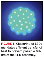
For most applications, the answer in terms of dissipating heat within an LED assembly involves the selection and use of thermally conductive and (usually) electrically insulating materials. This process of thermal management is the sufficient transfer of heat generated by the LEDs to ensure optimum performance over time. Typical end-use products include automotive headlights, street lights, traffic signals, etc., all of which have a critical purpose and mandate both maximum brightness and longest possible life. And a key contributor in the selection, configuration, and application of materials is the materials converter.
LED diodes consist of a die of semiconductor material impregnated, or doped, with impurities to form a p-n junction (Figure 2). When the LED is switched on – in other words, when a forward bias is applied to the LED – current flows from the anode (“p” side) to the cathode (“n” side). At the junction, higher-energy electrons fill lower-energy “holes” in the atomic structure of the cathode material, due to the voltage difference across the electrodes.
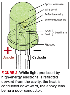
The energy released by the electrons in filling the holes produces both light and heat. The light, in turn, is reflected upward by a cavity created for that purpose, while heat is transferred downward into the base of the LED, and ultimately through a torturous path to where it can be dissipated into the atmosphere by convection, usually with use of a heat sink (Figure 3).
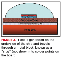
The process of light emission is called electroluminescence, and the color of the light produced is determined by the energy gap of the semiconductor. Since a small change in voltage can cause a large change in the current, care must be taken to ensure both are within spec and are as constant as possible. Otherwise, the performance of the LED can become degraded over time, even to the point of failure.
Is heat really a problem with an LED? It definitely can be a problem, and sometimes a difficult one. As the temperature rises within the LED, the forward voltage drops and the current passing through the diode increases exponentially, thereby leading to even higher junction temperatures. (Figure 4 shows how a small change in voltage can cause a significant change in current.) While catastrophic failures probably are rare, an LED module’s light output will diminish over time (Figure 5); efficiency will drop, and the color of the light emitted may change, due to shifts in wavelength brought on by the temperature rise. Wavelengths typically rise from 0.3 to 0.13 nm per °C, depending on the die type. As a result, orange LEDs, for example, may appear to be red, and LEDs producing white light – such as automobile headlights and street lamps – may have a bluish tinge. Other effects include yellowing of the lens, breaking of the wire, and die-bond adhesive damage. 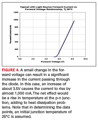
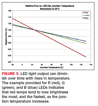
Figure 5 also suggests why white light created from RGB LEDs can appear to have a blue tinge as the junction temperature rises above its intended value. As the figure depicts, blue light falls off slightly less than green and much more so than red.
Proper thermal management in designing circuitry and modules containing LEDs is thus essential, and while various approaches are available, involving heat sinks, base plates, constant-current power supplies, and fans, the solution almost always encompasses the selection of materials for attachment, from thermally conductive adhesives to die cut pads, that are electrically isolating and thermally conductive (Figure 6). In most instances, a thermally-conductive/electrically-insulating pad will be the choice in transferring heat to either a heat spreader or a heat sink. 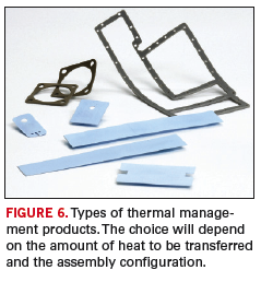
Designing an LED assembly – whether on a circuit board with other components or within an enclosure – first requires an assessment of the methods available for dissipating the heat to be generated by the assembly. Will the LEDs be through-hole or surface-mounted? Should a dielectric substrate be employed with thermal vias and a copper plate on the underside for absorbing and distributing the heat, or will the LEDs be mounted on a coated metal-core board that acts as a heat spreader? In other words, the initial effort is to determine how the heat is to be dissipated and the most efficient and effective heat path for transferring the heat.
Upfront design work for an LED assembly can be performed either in-house by the manufacturer, or with the assistance of an outside service, namely, a converter experienced in the dissipation of heat generated by electronic and optoelectronic components. In some cases, determining how best to dissipate the heat may benefit from in-depth thermal analyses using temperature modeling software for LED-based module designs.
Once the thermal path has been determined, the next step in designing an LED assembly is the selection and configuration of the thermal interface materials. Among these are liquid adhesives, die cut pads, etc. that provide the required thermal conductivity and electrical insulation. Such parameters as surface flatness of the substrate and heat sink, shape and metal used for the heat sink, applied mounting pressure, thickness of the interface, contact area, etc., may also be specified.
Various families of materials have been developed for thermal management in electronic and optoelectronic assemblies. Options include both off-the-shelf or custom formulations in specified thicknesses and configurations, as well as a variety of choices in types of material: conductive adhesives and greases, tapes, ceramic and metal-filled elastomers (also called “gap fillers”), coated fabrics, and phase-change materials.
Adhesives and greases have historically been the means of attaching a heat-generating device to a heat sink, and are relatively inexpensive. Pressure-sensitive tapes are also used for mounting components to heat sinks, as are elastomer gaskets, which can be coated with an adhesive on one or both sides, and can be die-cut into almost any shape. Thermal fabrics are typically fiberglass-reinforced, ceramic-filled polymer sheets that can provide both thermal conductivity and electrical isolation. Tapes, elastomer pads, and coated fabrics can be formulated to achieve specified performance values in terms of dielectric strength, thermal conductivity, and thermal impedance.
Phase-change materials change from a solid to a liquid during the process of absorbing heat at specified temperatures. The net result is the transfer of heat from a heat-generating device, such as a microprocessor, which is thermally coupled through the material to a heat sink.
Note that the role of a converter involves more than recommending the use of certain materials. For most requirements, the converter provides the finished part – for example, a die-cut gasket. Depending on the needs of the manufacturer, the converter should be able to perform the actual assembly work. While the requirement may typically involve thermal transfer, the binder, filler material, size and shape of the pad, type of adhesive, method of application, etc. are electrical insulation considerations. So too is EMI/RFI shielding, if needed. Then, too – again depending on the product – environmental sealing may also be required, since LED applications often entail operation under environmental extremes of temperature and weather, and even vibration. (Consider, for example, the vibration requirements for a sealed LED headlight.)
While LEDs seem cool to the touch, heat can be a significant problem, and could cause a product failure. Though excessive heat is not going to cause a color shift that results in a red stop light changing to green, the traffic signal could go out, or more likely, it could dim to the point of not being easily visible.
In designing LED-based products, the heat generated both by the LEDs and surrounding components, if any, requires serious consideration by the product designer, the materials engineer, and the converter contracted to provide a viable, cost-effective solution.
Chuck Neve is technical sales representative at Fabrico-EIS (fabrico.com); cneve@fabrico.com.
Press Releases
- Luminovo to Host Webinar on Instant PCB Pricing for North American EMS
- The Murray Percival Co. Adds Prey Limited’s Universal Product Inspection System to Its Portfolio
- Semi-Kinetics Acquires TM Soldering Solutions’ Phoenix IL Selective Soldering System for California Site Upgrade
- Altus Group Adds Scienscope's Newest Flagship X-ray Inspection System to its Portfolio


