Flux activators can become a catalyst for electromigration and dendrite growth.
There is no magic bullet to address component reliability; however, conformal coating can go a long way to extending product reliability within the harsh environments they operate – provided it is applied on a residue-free substrate surface. To ensure optimum adhesion of the protective coating, it is critical that assembly surfaces are properly cleaned prior to coating. In essence, conformal coating is a thin polymer protective film that, when applied, conforms to the PCB surface. Although conformal coatings keep the substrate’s surface dry and free from potential contamination, they are semi-permeable against humidity, depending on temperature and material type. For example, water permeability for polyurethane and acrylate coatings can increase from near zero at 20ºC to 14,000 g/m2h at 80ºC, comparable to the vapor permeability of Gore-Tex fibers. And bond strength, a measure of adhesion, is greatly reduced when applying a coating to a contaminated surface.
Failures under conformal coatings are related to remaining contamination, typically classified as ionic or non-ionic in nature. They may include salts, acidic flux activators, resin- and rosin-based residues, as well as organo-metallic complexes. Flux is used to clean or deoxidize the metal surface to be soldered; otherwise intermetallic bonding will not take place. However, any corrosive material left on the surface must be cleaned after soldering, as this may lead to climatic failure mechanisms.
For example, if flux activators, which are hygroscopic and acidic in nature, are exposed to moisture in the presence of conductive electrolysis and voltage, they become a catalyst leading to electrochemical migration and dendrite growth. Additionally, flux residues can lead to creeping currents, which can cause electrical shorts and/or bit failure in RF connections. In all cases, these are undesirable results.
Once we understand the substrate failure mechanisms, it is important to recognize how conformal coating itself can fail. Typical failures due to unclean boards are poor coverage, dewetting, incomplete polymerization, loss of adhesion and cracking. These can have several measureable root causes.
For one, ionic contamination levels are critical, as they analyze the substrate’s surface purity. High ionic contamination indicates the presence of a large amount of hygroscopic and conductive impurities. Due to the absorption of humidity, these impurities will build a moisture layer between the surface of the assembly and the coating. This will lead to coating delamination and possible failure. Also, if a protective coating is applied over non-ionic contamination such as organic resin, wettability is impaired and adhesion is compromised due to the different temperature-dependent expansion coefficients. Net result: Coatings can peel.
Another critical factor in achieving optimal conformal coating adhesion is substrate surface energy or surface wetting capability. This quantifies the disruption of intermolecular bonds that occur when a surface is created. Since ionic and non-ionic contaminants will lower the substrate surface energy, it is vital to minimize all residues.
So, how clean is clean for substrates, not just those targeted for conformal coating? For many Class 2 and 3 applications, many of which incorporate conformal coating as part of their process, cleanliness targets are typically set by IPC standards. Other times, cleanliness goals are mandated by the customer or set forth by the cleaning agent supplier. Aggressive but achievable limits can be as follows:
- Ionic contamination: <0.4 Ωg/cm2
- Surface tension: >40 mN/m
- SIR: >1x10E8Ω2
A clean substrate is critical to component reliability, as well as conformal coating integrity. Many cleaning methods are available. However, for consistency, it is best to incorporate either batch or inline cleaning equipment in the production process. Depending on the flux system used, these machines can clean with DI water or an engineered cleaning agent, either solvent- or aqueous-based.
There are limitations with the use of DI water. It may seem logical to clean OA fluxes with deionized water. But, water-soluble fluxes are typically activated by halides. In their organic state, these are difficult to remove with DI water. If partially ionized, they form hypo-halide solutions that can be very corrosive and result in electrochemical migration and contamination-induced leakage currents.
Also, due to its poor organic solubilization, DI water is not capable of cleaning RMA, no-clean, synthetic and highly polymerized “3D” flux residues. A change from eutectic, water-soluble solder materials to any of the aforementioned products will inevitably result in the formation of white residues on the assembly. Pb-free formulations are even more difficult to clean. Some aqueous cleaning agents have been shown to effectively clean substrates (reduce ionic contamination), as well as improve bonding and coating. This has been demonstrated not only with OA fluxes, but also RMA and no-clean fluxes.
Many other types of contamination and residue must be removed prior to coating: fingerprint oils and salts, fume residues from rework, adhesive residues and solder balls. To be safe, always clean your substrates, and certainly before conformal coating.
Harald Wack, Ph.D., is president of Zestron (zestron.com); h.wack@zestronusa.com.
Products might be “halide-free” at room temperature but, once heated, contain halogens far outside ppm limits.
So far, there is no official, government-mandated requirement forcing the production of halogen-free products and, therefore, the use of halogen-free materials, but the electronics industry is arguably moving in that direction. The drive to be halogen-free is being fueled primarily by increasingly environmentally-conscious customers, pressure from non-governmental environmental organizations and the desire by suppliers to be proactive.
What is lost on many in the electronics industry, however, is the underlying motivation of the halogen-free effort and the difference between halogens and halides. As part of electronics devices, halogens do not cause harm to humans or to the environment. The concern regarding halogenated materials has to do with the harmful byproducts that can be released into the environment at the end of a product’s life during the incineration process. Incineration of certain halogen-based materials releases dioxins into the atmosphere and these byproducts can be harmful to humans. Even though the majority of electronics products contain none of the halogens that cause harm, fear of having the term “halogen” associated with any electronics materials is pushing the industry to exclude halogens from electronics manufacturing.
Remarkably, many electronics professionals are unaware of the distinction between halides and halogens and this lack of knowledge can prove problematic. The below may help distill some of the differences.
Halides
- Ionic and have a charge (example Cl-, Br- , and F-).
- Added to solder paste to improve activity, encourage cleaning.
- Generally hydroscopic and can cause stability challenges.
- No clean fluxes normally encapsulate remaining halide constituents post reflow in the rosin to ensure post assembly reliability.
Halogens
- Covalently bonded group VIIA element without a net ionic charge (example Cl2, Br2, and F2); not available for fluxing activity at room temperature but only at high temperature.
- Primary source in electronics assemblies is in BFRs in laminates.
- Certain halogens – PBBs and PBDEs – present potential toxicity problems when incinerated (causing dioxins).
- Used in solder paste to enhance activity without impact to reliability
Halides and halogen materials have different reactions both at room temperature and at elevated temperatures. Ionic halide bonds are typically easily broken, which allows free halide to react with moisture and cause corrosion at room temperatures. On the other hand, covalently bonded halides are much more stable at room temperature and the bonds are not easily broken. At elevated temperatures – such as those consistent with soldering – the covalent bonds are broken and the halide can react with the oxide to clean and encourage wetting.
The test requirements for halide-free and halogen-free materials are completely different as well. While international standards have been set for halide-free, high reliability solder interconnects and the test procedures have been well-established, the same cannot be said for halogen-free. Table 1 further illustrates these differences.

Table 1. Classifications, Test Procedures and Standards for Halide-Free and Halogen-Free.
As the chart shows, the three primary standards for halogen-free do not equate to 0 ppm halogen. Therefore, the majority of today’s so-called “halogen-free” materials are not truly free of halogens. To complicate matters further, the testing regimen for halogen-free materials can also be challenging. As halogens have a neutral charge and cannot be detected by standard ion chromatography, they must be converted into ionic halides through a combustion process. This means that many so-called halide-free materials may, in fact, contain hidden halides. Under the current analytical methods, testing occurs during a state in which chemical bonds are not broken, but are kept under isolation in a neutral charge format. When these chemicals are heated – as happens during the solder reflow process – the bonds are broken and halides can then be detected. So, many products that claim to be “halide-free” might be so at room temperature but, once changed during the manufacturing process, can contain halogens far outside of the current recommended ppm limits.
Because covalently bonded halogen delivers many benefits for the soldering process, many materials developers use small amounts of halogen – just below the ppm limit – in their formulations. While this is legitimate, the danger is that excess halogenated materials can be added during the manufacturing process. The only way to ensure a truly halogen-free product is to have zero deliberately added halogens in the formulation and products constructed of the purest raw materials available. The situation is made more complex by the testing challenges halogen-free introduces, with manufacturers largely relying on their suppliers to confirm the purity of the materials they are receiving.
While the jury is still out as to whether or not halogen-free government mandates will come to pass, manufacturers that understand the halogen-free/halide-free distinction will be in a far better position to navigate any legislation that may be imposed.
Jie Bai is a chemist at Henkel Electronics Group (henkel.com); jie.bai@us.henkel.com.
Considerations for incorporating fuel cells.
Cost, durability, size, weight, thermal and water management are major challenges to the commercialization of fuel cell technology in commercial and military applications. Many manufacturing issues need to be solved in order to bring fuel cells to the mass market for naval applications. Manufacturing and acquisition costs can be reduced significantly by reducing or eliminating the use of precious metal catalysts, such as platinum and rare earth metals, to reform fuels.
In light of these challenges, the Center for Advanced Mineral and Metallurgical Processing (CAMP) at Montana Tech is developing fuel cell manufacturing and materials technology for the Office of Naval Research ManTech Program to investigate electroless plating of palladium and palladium alloys on stainless steel substrates. This research includes laboratory work and an extensive literature search of electroless and other methods used to form palladium and palladium alloy membranes. This month, we summarize the findings.
Electroless plating is a chemical process that catalytically reduces metal ions in an aqueous solution and deposits that metal on a substrate without the use of electrical energy. The process is similar to electroplating, except no outside current is needed. A controlled pretreatment sequence and plating process are critical to produce good adhesion of the metal to the substrate.
In the electroless plating process, the driving force for the reduction of metal ions and their deposition is supplied by a chemical reducing agent in solution. In the case of palladium and palladium alloys, the reductant is typically hydrazine. This driving potential is essentially constant at all points of the component surface, provided solution agitation is sufficient to ensure a uniform concentration of metal ions and reducing agents. Electroless deposits, in theory, have a very uniform thickness all over the part. The electroless process has definite advantages when plating irregularly shaped objects, especially those that are difficult to plate by conventional means.
Hydrogen flux calculations. A unique property of palladium is that hydrogen gas diffuses through the metal. This characteristic is commonly used to produce very pure hydrogen using a palladium membrane. The flux of hydrogen gas through a palladium membrane is dependent on temperature, hydrogen partial pressure, and membrane thickness. From a metal cost and flux standpoint, it is desirable to make the palladium membrane as thin as possible. Therefore, instead of using pure palladium foil membranes, many researchers have investigated plating palladium onto porous metallic and non-metallic substrates.
A substantial amount of research has investigated hydrogen flux measurements through palladium and palladium alloy membranes. Hydrogen flux is the rate of hydrogen passing through the membrane per unit area. Flux is typically denoted by the formula: 
where:
NH2 = hydrogen flux in moles per second per sq. meter
K = permeability (moles per meter per sec. per pascal) PH2, ret , PH2, perm = the partial pressures of hydrogen on the retentate and permeate sides of the membrane, respectively (pascals)
XM = membrane thickness (meters)
According to Morreale,1 the exponent (n) in the above formula is equal to 0.5 if the rate-limiting step in the hydrogen transport mechanism is diffusion and that transport is unidirectional. However, the assumption that diffusion is the rate-limiting step may not be accurate. Morreale found that the optimum value for the exponent was greater than 0.5 in experiments as the hydrogen pressure on the retentate (upstream) side of the membrane increased. The optimum exponent value was determined to be 0.62 at retentate pressures up to 9,000 pascals and temperatures up to 1173 K. For this study, hydrogen flux values varied from 0.002 to 0.062 mol/s/m2, with greater values associated with higher pressure differential and higher temperatures. Experiments described in this study were conducted with relatively thick palladium membranes (XH ~ 1 mm).
Data review and statistical analysis. Rothenberger in 2004 tabulated data from a large number of hydrogen purification studies.2 These data were imported into Stat-Ease statistical software and response curves created. The following figures show the effect of several variables on the trend for a particular response. These figures are for those sets of data where the plating was by electroless deposition and the permeate side pressure was atmospheric using a sweep gas.
The membranes were plated onto either aluminum oxide or porous stainless steel. The variables examined were palladium membrane thickness (µm), reciprocal temperature (1000/T K), and electroless versus other plating techniques. The responses were flux (mol/s/m2), permeance (mol H2/(m2•sec•Pan)•1012 (not shown), and permeability (mol H2/(m•sec•Pan)•105. The noted factors of 10 were used to make the axis numbers easy to read.
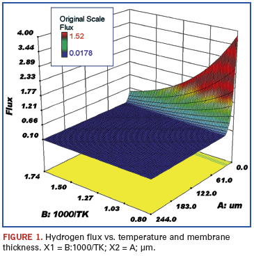
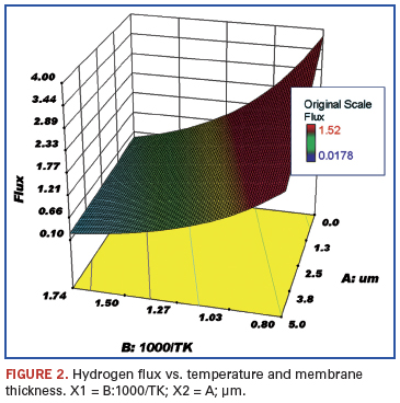
Figures 1 and 2 show the response of hydrogen flux with respect to changing temperature and palladium thickness. As the temperature is increased, the hydrogen flux goes up; flux is poor at lower temperatures, but is much greater the thinner the membrane and the higher the temperature. The flux, of course, at a membrane thickness of zero is only a mathematical projection. The lowest temperature shown is 300ºC, since palladium membranes must be operated above 300ºC to ensure a defect-free membrane. The usual operating temperature is in the range of 450º to 500ºC, and the desired membrane thickness is less than 5 µm. The problem of operating palladium membranes below 300ºC is that a mixture of body-centered cubic and face-centered cubic hydride solid solution phases is formed. Above 300ºC only a single solid solution phase exists. This problem is twofold; i.e., if the membrane is cycled above 300ºC and then back to ambient temperature several times, stresses are formed because of the different thermal expansion coefficients of the phases. The resulting stresses can cause defects in the membrane. One way to minimize the cycling problem is to treat the membrane at elevated temperature in a vacuum to remove dissolved hydrogen. In addition, the flux of hydrogen at ambient temperatures through palladium is very small, whereas it is much higher at elevated temperatures (300º to 600ºC).
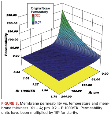
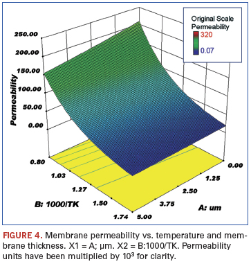
Figures 3 and 4 show the response of the membrane permeability to hydrogen with respect to changing temperature and palladium thickness. As expected, this follows the same trend as shown for hydrogen flux.
The fact that hydrogen flux increases with increasing temperature and decreasing palladium thickness is not surprising. The data appear to indicate room for improvement; higher temperatures and thinner membranes should result in even greater fluxes. However, there are practical limits to both these parameters in terms of material limitations. For example, it may be possible to deposit even thinner palladium membranes on substrates, but the integrity of these membranes will be compromised, especially when subjected to extreme temperature cycling. The same holds true for the higher temperatures needed for increased flux; many of the materials currently being used in purification systems are at their practical temperature limits.
References
1. B. D. Morreale, et al, “The Permeability of Hydrogen in Bulk Palladium at Elevated Temperatures and Pressures,” Journal of Membrane Science, 212.1-2, 2003, pp. 87-97.
2. K. Rothenberger, et al, “High Pressure Hydrogen Permeance of Porous Stainless Steel Coated with a Thin Palladium Film via Electroless Plating,” Journal of Membrane Science, 244.1-2, 2004, pp. 55-68.
ACI Technologies Inc. (aciusa.org) is the National Center of Excellence in Electronics Manufacturing, specializing in manufacturing services, IPC standards and manufacturing training, failure analysis and other analytical services. This column appears monthly.

A look at the top candidates for creating the age-old cells.
It has been close to 30 years, but it is only now, as the solar cell industry strives for increased efficiencies, that selective emitter is being taken seriously. Indeed, one reviewer of the past Intersolar North America Expo noted that just about every crystalline-silicon cell manufacturer worth its salt is now devoting R&D resources to its development.1
It’s easy to see why. The energy-converting heart of the majority of silicon-based solar cell is its p/n junction. This is normally formed in the early stages of cell manufacture by firing the wafer in a phosphorus-rich atmosphere, thereby diffusing a uniform, planar layer of phosphorus a few hundred nanometers into the upper zone of the wafer. Here, photons of sunlight release electrons that migrate through the silicon to the cell’s front face, where they are captured by the grid of silver conductor fingers printed on the cell’s top side. Once captured, they flow around the circuit to the aluminium contact on the cell’s reverse side to rejoin their electron-poor, “holey” atoms, and in so doing, they create the cell’s electrical current.
Maximum efficiency relies on everything working optimally – on the photons generating sufficient electron/hole pairs, and on these migrating to the right places and being collected properly. Herein lies the rub. The very material that is instrumental in giving the p/n junction its functionality also forms a significant barrier to light: The top part of the cell where the phosphorus is most concentrated can in fact “waste” a massive 30% of incident light in the blue part of the spectrum.
Selective emitter mitigates these losses by limiting higher concentrations of phosphorus to areas directly under the silver collection grid. Here, the phosphorus can do no harm, as this area of the cell is in shadow, and at the same time, it improves the contact between the silicon and grid, facilitating electron migration. The area between the grid, on the other hand, contains relatively low levels of phosphorus, optimizing the cell’s blue response and increasing efficiencies.
That’s the why; the how is a little more complex. As is inevitable for a technology that has been kicking around for so long, numerous techniques have been developed in labs over the years, all promising to create the definitive selective emitter solar cell. Time will tell which technologies win out, but in the meantime, we can pare the likely contenders to six or seven main categories.
In most of these, the wafer is first doped with far lower phosphorus concentrations than the current industry standard. Extra dopant is subsequently added in the areas directly in contact with the silver conductor grid. This can be achieved in several ways.
Perhaps easiest and cheapest, if not most effective, is to use hybrid pastes. These are standard metallization pastes containing added dopants, enabling both to be printed at the same time. The phosphorus then diffuses into the silicon as the paste is fired.
Another way of adding extra dopant is to screen-print it onto the wafer in a grid pattern that is perfectly aligned to the silver collection grid that will subsequently be printed over it.
An alternative to printing is selective diffusion, by which a second doping step is performed prior to the metallization step, but with the areas between the silver grid fingers masked off so that only the grid area is doubly doped. In a slight variation on this theme, semipermeable masks are being developed that enable the wafer to be doped to different concentrations in a single step.
Laser doping, developed by the University of Stuttgart’s Institute for Physical Electronics, laser-writes the phospho-silicate glass (PSG) layer that forms on the wafer surface during the standard diffusion process, driving more phosphorus into the silicon under the area where the silver grid will be printed. The PSG layer is then removed, as in standard processes.
In the etchback process, the wafer is doped at high concentrations, after which the wafer surface in the areas between the fingers is etched away, taking with it much of the phosphorus it contains. This can be achieved using printed etching pastes, or by using etch masks and a wet chemical etching process. A variation of this replaces the standard doping process with doping paste, which is printed across the entire wafer and then etched off
where appropriate.
One of the most complex but interesting alternatives is the buried contact process, whereby deep trenches are laser- or saw-cut through several passivation, doping and emitter layers. These trenches are further doped and then metallized, creating a collector grid that extends deep into the wafer and is fine enough to reduce the shadowing effect, and boost cell efficiencies, enormously.
All these approaches come with pros and cons, but are interesting enough to attract the solar industry’s attention and resources. To be serious contenders, however, they must be easy to use, increase production efficiencies, and their added process steps should not compromise the already delicate structure of the solar cell, either in production or in the field. To achieve this, the environments in which they are to be introduced must be capable of delivering repeatable alignment accuracy and, given the fragility of silicon solar cells, extremely careful handling at all stages during the process, all without compromising throughput rates.
References
1. Tom Cheyney, “Intersolar North America 2010 Redux: PV Multiplicity, Surging CIGS, Single-Crystal Silicon, and More,” PV-Tech.org Daily News, July 28, 2010.
Tom Falcon is a senior process development specialist at DEK Solar (dek.com); tfalcon@dek.com.
A first-of-its-kind panel of pick-and-place OEMs offers their take on flip chips, on-board inspection and the future.
Are today’s component placement machine platforms sufficient for tomorrow’s technology?
That was the question several leading placement OEMs addressed during a first-of-its-kind roundtable in late October.
Under the auspices of SMTA and moderated by CIRCUITS ASSEMBLY, the 90-minute roundtable brought together high-level representatives from Assembléon, Essemtec and Universal Instruments, with Juki joining later to complete the picture. It was a sales-free zone: No audience was present. Instead, the competitors were asked to set aside the gloves for a few hours and talk technology and markets.
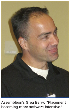
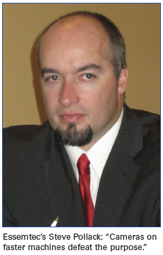
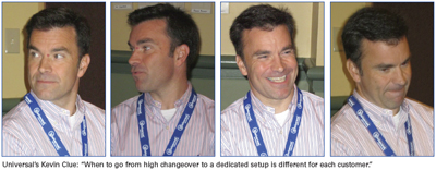
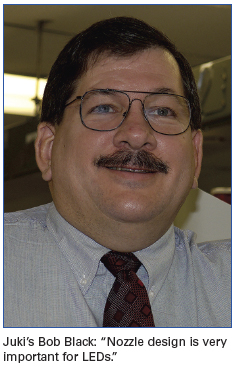
Joining us were Greg Berry, global director, medium volume solutions at Assembléon; Kevin Clue, regional sales manager at Universal Instruments; Steve Pollock, Essemtec vice president of sales; and later, Bob Black, president and CEO of Juki Corp. What we heard was unprecedented candor and consideration about the challenges for electronics manufacturers today and tomorrow. Excerpts of the conversation are below; for the complete transcript, visit circuitsassembly.com.
CA: Given the capability of your machines today, what conditions must be met to be able to place next-generation packages in volume?
SP: Most of our customers are not in the 24/7 production market, but we deal with a lot of government institutes, a lot of people doing high-tech things, so we need to be able to do 01005s, 0.3 mm chips, QFNs, just in lower volumes. With our new platforms, we are moving into upper medium-volume pick-and-place, up to 24,000 placements per hour. These platforms are a completely new design. Linear motor drives, x-y accuracies of 0.02 µm.
GB: We have been doing 01005 in volume for four or five years. What we see on the forecast is not an issue. I used to be a manufacturing engineer, and you look at the bottom termination components and QFNs – for us, it’s very simple to process those. The issue is paste deposition, the process behind it. The pick-and-place is pretty simple. The BTCs are not much of a challenge. We’re building machines to handle flip chips. If you buy from one of the top guys, you’ll have a machine that unfortunately will probably last you for the next 10 years. [Laughter.] It’s horrific. [Laughter.]
KC: The 005005 [Ed.: metric 0201] package coming down the pike is a challenge from a manufacturing and pick-and-place perspective. Our lab in Binghamton, NY, is focused on those new package designs, but that’s the only component we’re kind of getting our arms around. The 01005 nozzle technology was something we spent a lot of time developing to get the yields. Placing an 01005 is a lot different than placing an 0201. A package two-thirds the size of an 01005 will be interesting.
CA: Is the trick in the vision, the nozzle, the software?
BB: Measurement is not the issue. Machines can see almost 40 pixels across the short side of an 01005. For 005005 packages, even without doing anything, we will have 20 pixels on the short side. More critical is the nozzle construction. The nozzle cannot extrude over the side of the part at all. You could dislodge adjacent parts. We’ve gone to “no-blow” technology. With larger parts, you used to reverse the vacuum technology. But with 0402s and smaller, doing that would blow the previous part off.
GB: From Assembléon’s perspective, it’s more the vision of the components. Every time you think you get your arms around what chipmakers are doing, they come out with a completely different package, a completely different array, and it makes you rethink the algorithms.
The positioning systems, the camera technology, everything you have today – if you look at where we were 10 years ago, there are still a lot of people using 10- or 15-year-old placement systems. I think the technology we have in systems today is good for the foreseeable future, including 005005. It’s more vision, algorithm-driven and some nozzles; 01005 and 005005 nozzle technology will be an issue because oil on your fingertips could clog the nozzles.
CA: There’s been discussion for two or three years about post-placement inspection supplementing or perhaps even supplanting post-placement AOI. To what degree have you looked at that, and what are the pros and cons?
BB: Camera-based inspection is neutral to the footprint of the machine. It doesn’t slow the line; bad boards are sidelined, which will take far less time than it would take if they deal with it after soldering. It’s a question of price vs. performance. The real key to this is not just the inspection part of it. It’s when you have a problem in assembly, when do you catch it? After you have built 300 boards, or at the first or second one? After you find the mistake, how do you figure out how it originated? Which machine? Which process? The WIP cross-failure analysis allows an engineer to quickly pinpoint when and why a problem occurred. We view this as a factory control issue. Fewer engineers are running more lines. With this system, you’d be able to control every line.
SP: Our machines look at components using a fiducial camera. It’s not like what an AOI would do. If you put this technology on a faster machine, it’s defeating the purpose. I think they should be kept separate. For volume, it doesn’t make sense.
KC: We somewhat agree. We see some value there, but AOI in a placement machine is a little too late. If you’re building in a lot size of one, as a lot of our US customers do, it’s a little late to look at the part after it’s been built. Universal’s approach is to use process diagnostics in the machine, using dynamic and adaptive technology for X, Y and Z at placement and pickup. We’re looking at parts before putting them down. We monitor nozzles as they are used, making sure they are correct and not defective.
CA: As a follow-up, would that by extension mean post-placement AOI is not necessary?
KC: I think there is a market for that, but it’s not Universal’s sweet spot. I think there’s a market in Asia where they are building the same thing all day, every day.
GB: I agree. I don’t think you can ever get away from post-placement inspection because, if you are building a million iPhones, you can’t afford building bad product because the tray was loaded backward. At the other end of the spectrum, on reliability-critical – military, medical, implantable devices – you have to do 100% inspection. You’ll always have to do inspection at some level. It’s going to become more mainstream. Right now it’s 80% don’t, 20% do. I think you’re going to see a switch soon.
CA: Insofar as a hybrid machine doing placement and post-assembly inspection?
GB: We’ve looked at this quite a bit. But if you’re trying to push out 100,000 cellphones an hour, that’s wasted placement capacity. Why take up that real estate inside the machine to do an AOI function? You’re going to murder the output of the line. Where it makes sense is the low end, because volumes aren’t as high; capabilities aren’t nearly as great.
KC: I would even question that because what does an AOI cost now: $40,000 or $50,000?
SP: Minimum, for a batch.
GB: But if you need x-ray…
KC: X-ray’s a different story. Some of these guys putting AOI inside the placement machine, that’s not x-ray. They are looking at presence/absence, X,Y and theta.
GB: That’s true.
KC: You can buy a $40,000 automatic machine with software developed over many, many years; let’s all stay with our key competencies here.
GB: I couldn’t agree more. [Laughter.]
CA: In looking at operations with dedicated placement machines vs. ones with high changeovers, is there a rule of thumb for the type of line you should buy?
BB: We have kept the same philosophy worldwide: Make all machines flexible. China tends to use fixed banks, with nothing on the back of the machine. In the US, most customers are totally flexible. We try to make all machines the same changeover time, regardless of speed.
GB: Internally, because we have such a broad spectrum, we’ve had to give people a rule of thumb. The volume machines are a lot more advanced than a few years ago. Volume machines can be changed over 10, 12, 20 times a day and still maintain good output. If batch sizes are below 100, it starts making sense to look at even more flexible, lower-speed machines, and then rack-and-stack multiple lines. If you can turn on the machine and let it run for an hour, it makes sense to buy dedicated high-volume lines capable of quick changeover. A lot of customers can do 10 NPIs, and it takes 10 to 15 minutes on a brand new, never-seen-before product, from CAD to running product. It doesn’t matter whether it’s a volume line or a flex line. That threshold is getting pretty low as to what makes sense. The biggest key I see is commonality, common lines. Maybe the batch size is enough to warrant a certain level of output, but then you just mimic that line every time.
KC: I don’t think you can quantify when it makes sense to go from high change to a dedicated setup. Every customer is different. Go to any contractor on the globe and ask the plant manager what their biggest issue is: It’s parts availability. They’re not able to ship their product on Day 1 of the month because they don’t have the parts to build the product. They have the equipment, the resources; they just don’t have the parts. So everyone is going to quicker change because they have to build in smaller lot sizes, and quicker change requirements have increased need for software.
CA: Perhaps the fastest-growing segment of the industry is flip chip. How are you responding to that?
BB: Of the placement machines today, probably the more accurate ones would be in the 15 to 20 µm range for true center position placement accuracy. For true flip chip, you need 10 µm or below. More placement platforms will be coming with that level of accuracy. For flip chip, you get into thermal stability. Just a few degrees over the day could mean microns difference in accuracy. Machines can be made out of granite and ceramic to get a little more out of the thermal expansion. You’ll see these in the next few years.
SP: Right now in the US, we haven’t seen a lot of this. In Europe, certain people are talking about it. It’s about how it’s presented, how we are picking it up; do we have to pick it from a wafer? Do we have to put it into a flux station? Is it pre-fluxed? There are a lot of different thoughts about that. We are addressing it, but it’s more on a case-by-case basis.
CA: So it’s custom machines?
SP: It’s an add-on.
GB: We see flip chip in two segments: high volume and everything else. The high volume, we’re creating additions to the AX with twin-place robots that have 20 µm accuracy, linear fluxers, and what we see on that end is that tape-and-reel is standard. That’s how everyone is presenting these things: no real need for wafer feeders or anything like that. That’s one way we are attacking it, with the high-volume A series and dip fluxers and whatever they need for process, but not really worrying about the wafer handling.
On the flip side, Yamaha is releasing a new machine to go after people needing wafer handling, lower volume – maybe 3,000 to 4,000 cph – and looking at pulling out a 12-in. wafer, dip flux and flip them and do everything. Volume-wise, there doesn’t seem to be a middle ground. You’re either prototyping or doing a lot of volume.
CA: Can you handle both those sectors on a single platform?
GB: For us, the machine we’re using for prototyping could delve into high volume, but it depends on where the customer’s requirements fall. If you have 100,000 cph for chips and need three or four or five flip chips placed, it could keep up. The cellphones are driving more and more to flip chips; they are putting more on there to get better space utilization on the phones, so you’re starting to need 20, 30. Those guys don’t need wafer handling; just pick it, dip, place. The high-volume machines won’t handle the wafers at all. Indications from everyone are that for volume, all the sorting will take place offline.
KC: We all have our niche. Universal’s position is one of accuracy, so our standard platform can manage 10 µm in accuracy, which is, I think, an industry-leading spec. Five years ago, you had to buy a flip chip bonder for $500,000 and pick-and-place machines for $300,000 or $400,000, and you have an $800,000 solution because you are building system-in–package, and you need flip chip and discrete. People don’t want to spend on two systems, two sets of software, two sets of operating expenses, two direct labor expenses and so on. We’re seeing a merger of surface mount and microelectronics, and the requirement is for platforms to be able to accommodate everything. You need the speed of surface mount and the accuracy of the micro side. You have to have the accuracy and the speed, with direct die feed capabilities.
I do agree that the smaller guys – who don’t need the speed but want accuracy, small feature recognition capability, all sorts of tooling, dipping stations – they need all the bells and whistles.
We can migrate into volume so the guy picking from waffle pack could morph into picking from tape-and-reel and wafer all on the same platform. That’s our wheelhouse – to have a modular platform that can go from building one all the way to high-volume flip chip assembly.
CA: Certainly assemblers like to dial down the WIP. So with parts availability an issue, have you seen EMS companies building partial boards and waiting for the final parts, or do they wait to start until they have the whole kit? This would have a direct impact on changeover, of course.
KC: Yes, that has a direct impact on changeover.
GB: When you said software is so critical to that, it really is: being able to manage what you do. As you are bringing the kit to the floor, you notice, “Oh, we’re missing three of the components.” If the philosophy is we don’t build unless we have a full kit, the entire production schedule turns on its head. To have the software to be able to adapt to that, to do common setups and to be able to quickly change over, that’s crucial. I see both. Some people will say, “I’ve already got it set up. I’ll build it out.” Others, whom I think have a little better handle on the business aspect, will make the quick change. In my opinion, it is an issue, but there are no standards as to how to tackle that issue.
BB: Most are waiting for the complete kit; those who aren’t are adding the last few parts by hand at the end. If they build without all the parts, they always could choose whatever parts are left to place and block the rest. But for most complex parts, the EMS companies are using hand soldering or an automated tool. We see very few people running them back through the machine.
CA: With LEDs, one of the options is getting the light output correct, parts with the right intensities and the bin codes all matched up. What do you do in that regard to tackle that?
SP: We have quite a few customers doing LEDs, mainly because some of our platforms have very large board sizes. We created a lot of special nozzles for these, how to pick up over the domes without separating them from the substrate. To date we’ve made 700 to 800 custom nozzles.
CA: Does it require a software upgrade?
SP: Not at all. It’s amazing how huge this market is. If you start a company making LEDs, you can make money, because there is room for everyone, and everything is going to LED: from the small guys with a niche to the guys trying to replace all the traffic lights in every municipality. And custom LED lighting. It’s a really cool industry. It’s going to benefit everyone. And how cool do those LED lights look – come on! [Laughter.]
BB: The important thing is a good vacuum feed on the part. If you have a dome, and have to hold the part straight, you have to get down under the collar to hold the dome. Nozzle design is very important for LEDs. The other thing that helps with LEDs is machines with rotary heads have to be more careful; when spinning at high speeds, the centrifugal force needs a good vacuum grip, or you would lose the part. LEDs are bin-sorted for intensity. If you lose too many, you will have blotchy intensity with the lights. That said, the rotary head can be used; sometimes you slow it down a little or optimize the nozzle design.
GB: Philips invented the Lumaled lighting and was on the front end of that for 10 years or so, but the process was hell; it just wasn’t really a process. For automotive, we saw the LEDs really come on strong. We developed a lot of customized software that has now become productized; it has turned into our setup verification software. The key things are monitoring the bins; monitoring how many boards you have left to produce on the reels left on the machines; if it gets below a threshold, shutting machines down and not letting it put more boards in until new reels are scanned. Whenever you make something idiot-proof, you find a better idiot. [Laughter.] We’re adding things like moisture-sensitive, timing, making sure if it goes into a bake cycle that you back that all out; if it goes into dry box, stopping it. Also, some of our customers dynamically change the placement program, so [some] don’t care if it’s seven different LEDs, as long as the intensity is the same. Therefore, you have to change all your resistor values on the board to dynamically keep up with what’s being placed. On the other end, if you are building for the BMW 7 Series, one reel of parts has to have everything for that entire car. It’s a completely different set of requirements for the binning and LED trapping.
CA: It sounds significantly more complex than traditional SMT.
GB: It goes so far beyond normal setup verification, it’s not funny.
BB: Absolutely. You have to have software flexibility to optimize the feeder position. It’s a software modification to the current platform.
CA: As a standard rule, would you need additional feeders ready to accommodate all that dynamic changing of parts?
GB: At that point, it depends on volume. For a little guy, for the feeders, no. It takes nothing to change the Yamaha electric feeders over. For a volume environment, there are typically only two or three reels anyway, because they want to keep the WIP fairly small, and minimize the opportunities for partial reels left.
KC: The automotive market tends to push you in those areas mentioned. The other market for LED is commercial lighting, which drives other parts of your business. In Asia, they want to replace these 4-ft. long ballast assemblies in every contract manufacturing facility. They drive you not only on the pick-and-place technology for a little LED, but on a board technology perspective as well, so the Asian marketplace is driving toward 1.2-meter long boards. They aren’t very thick …
GB: They are the same as a fluorescent tube …
KC: The weight isn’t an issue. It’s the physical placement area that becomes the challenge. Universal would handle that board differently. Board size – length – is becoming important. Our standard platform is over one meter, and we’re driving toward 1.2 meters. The challenge from our side is to be able to accommodate SiP: tiny little thin boards that are basically flex circuits; being able to pick-and-place die onto these flimsy little substrates; and then being able, with the same machine, to accommodate this 1.2-meter long board. That is a challenge.
CA: Plated through-hole components: Will they die out in our lifetime?
GB: I don’t see it. You can’t handle the power with an SMT component. It’s physics. There’s no way around it. They may die due to neglect. Even with us driving to lower power consumption, you still have to be able to charge it, to handle 120V AC and knock it down to something you can use. To do that, you have to have through-hole components. SMT can’t get there.
KC: I agree. We still see a lot of through-hole components in automotive and in consumer electronics. Those who aren’t focused on board size, who aren’t constrained by density, they have current requirements, power requirements; they can’t do it with surface mount. We still build a lot of through-hole machines today. [Research firm] Prismark has through-hole going through 2020.
BB: They will outlive me [laughs]. That’s one reason selective soldering has become so popular. You still have those few PTH parts and connectors on many boards.
GB: In my opinion, the only way through-hole dies is if the government forces us onto DC instead of AC. That’s the only way you get away from them.
CA: It sounds like there isn’t much out there right now that existing platforms can’t handle, but 005005s and extreme LEDs are pushing the boundaries right now?
GB: Process-wise, once you get it figured out, it’s not too bad.
KC: The biggest challenge we have in surface mount is what we are being pushed to by our customer base. Our customer base is trying to take money out of the assembly. They are taking skilled workforce out of the equation and putting unskilled workforce into the equation. There are variables from a parts perspective, parts number issues, traceability issues. The challenge we have is, how do we still make good product when you might not have quality engineering staff, quality technician staff, quality raw materials? When you perhaps don’t have the same level you had 10 years ago, that’s a change that must be accommodated in the machine. The bigger issue is figuring out how to deal with the change in the infrastructure of our customers.
BB: In China in particular, we have gone to almost a totally graphic interface where you touch a picture on a touchscreen. There’s very little verbiage left. The level of education and amount of training people get in factories is really minimal. It’s a continuing problem. The other problem is many run it until it breaks. They don’t do maintenance. Based on that, we’ve altered the way we build the machines.
GB: It’s not so much the technology we see, but it’s all the elements surrounding it, all the elements outside the machine’s scope. It’s becoming more software-intensive. It’s why we keep saying we need to stop staring at our belly button and look at what’s happening in the outside world. The technology we will figure out. Given enough time, you can always figure the solution to placing whatever comes next.
Mike Buetow is editor in chief of CIRCUITS ASSEMBLY; mbuetow@upmediagroup.com.
Lab tests reveal decreased print variation and question whether smoother surfaces show better paste release.
Nanotechnology is used to create new structures and components size 100 nm or smaller. A nanometer is one millionth of a millimeter. That’s approximately one fifty-thousandth the diameter of a hair.
This author invested considerable time researching limitations of the field of stencil fabrication and looked at crossover technologies that could be introduced into this specialty industry. Reviewing several potential candidates, nanotechnology1 rose above all others.
Typical coatings mechanically adhere to the surface of the target material to which they are applied. These types of adhesions usually are weak, which limits their effective life through delamination, etc. This leaves them susceptible to wear and tear that, after being exposed to mechanical types of cleaning, cleaning agents and even stress-inducing flexing of the foil, will cause them to flake. This in turn could contaminate the assembly.
Some nanotechnology coatings do fall into this category. From the author’s experience, the adhesion process of the coating is vital to a successful nanotechnology product for the stencil printing industry. Concerns include whether the coating has deviations within it, such as thickness variations due to pooling, or requires several coatings to be built up for durability. This could lead to inconsistent stencils.
Regardless of coating method, longevity and repellent characteristics, how may this new technology help the masses? Given that area aspect ratio is a performance driver, coating the bottom side of the stencil (substrate contact side) will affect a different factor of performance. With less adhesion of solder paste on the bottom side, cleaning and process maintenance may be easier.
There have been suggestions of users improving understencil cleaning process by significant factors with the introduction of nano-coated stencils.2 Based on lab tests, not only does this author concur, but observed a few other phenomena worth mentioning.
Stencil priming. The typical first few prints seem to prime the stencil apertures in typical stainless steel stencils (Figure 1). In most SMT assembly lines, it is not uncommon for the first two to four prints to show variation. This was not witnessed while printing with a nano-coated stencil. The first print was the same as the last, as shown in the real-time 3D volumetric data plots (Figure 2).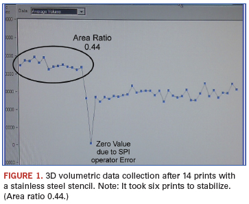
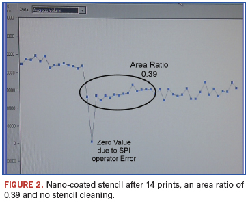
Paste wait time response. Printing was stopped and 30 min. allowed to elapse before printing was continued. Without any stencil cleaning, the first print showed no signs of deviation. And although there were symptoms of more variation than previously, it still was within a tolerable range for consistent assembly process control (Figure 3).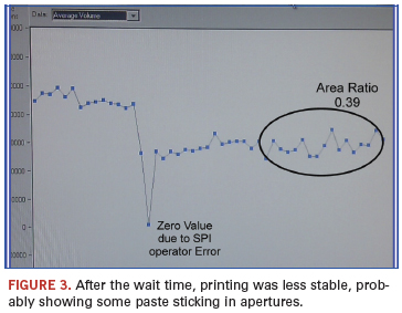
Stencil separation speed. Changing the speed of this parameter from 1 mm/s to no stencil separation speed control (maximum speed) revealed no noticeable change in the paste volume, other than an increase of overall mean volume (Figure 4). It is hypothesized that with less surface energy within the apertures, the print medium separates more efficiently due to a quick shearing effect, akin to pulling a soft stringy cheese and sharply snapping it to break it. 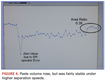
Conversely, a slow separation of the solder paste appears to create a kind of laminar flow, whereby the flux vehicle will separate from itself more easily than at the surface of the aperture wall. More investigation in understanding this phenomenon will be useful in identifying the physics underlying the surface tensions created by the print medium and area ratios. However, the focus here is on altering the surface energy characteristics to permit better release of material.
Nano Coating Integrity
Although a nano-coated stencil may show promise, how do you know it is coated? How do you know it is durable? New terminology will be introduced, such as hydrophobic/oleophobic, these being water and oil repellent, respectively. As water is not a printing medium used, more viscous materials such as flux in solder paste (fluxophobic) will need to be tested and verified. A number of tests can be applied, one being the contact angle test using a goniometer. Such metrology usually isn’t readily available, so taking a low angle lateral digital photograph and performing measurements using a PC works too.
For solder paste printing, flux would be an ideal medium to use for this. By applying a droplet of the flux material, the angle of contact reveals the nature of the surface energy (Figure 5). This test can be repeated for durability so that wear characteristics and, therefore, effectiveness can be ascertained after many print cycles, understencil cleaning cycles and stencil washes have been imposed on the stencil.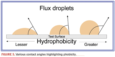
An easier practical test carried out on different materials consisted of a droplet/bead test and a run test. These test samples were cleaned and treated with a simple wipe on nano coating chemistry that has a self limiting nano layer. As the specific fluxes were not available at the time, a light oil similar in viscosity to flux was substituted. This is a comparative test, and the concept was to see how treated and untreated stencil materials behaved with respect repellency. Hydrophobicity is not a relevant test for performance.
Stainless steel SRA (stressed relieved annealed). This material is a little more ductile than other stainless steels and is used throughout the stencil industry for most standard products. The drop/bead and run test (Figure 6) clearly displays the difference in the level of oil repellency between nano-treated and untreated. One phenomenon observed was how the untreated run test would not leave the base material, whereas the treated material would run off to the paper below. Both treated and untreated samples are in contact with the paper. This was consistent with all tests with the different stencil materials used. This could be an interesting discovery of how surface tensions may also factor in paste release, with not just the aperture walls but the rims of the upper and lower surfaces playing a role. This would reinforce the idea that underside stencil cleaning paper will absorb and remove contamination more efficiently on a nano-treated stencil compared to an untreated stencil.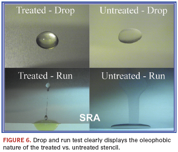
Stainless steel fine grain (FG). There is an increasing interest in the development of fine grained materials because this could be a solution for providing higher mechanical strength alloys.3 With finer grain structure, it is proposed that the newer laser cutting process will provide a smoother wall and thereby better paste release. The bead and run test (Figure 7) confirms that an untreated “smooth” surface does not repel the oil and, therefore, questions the theory that smoothness releases better.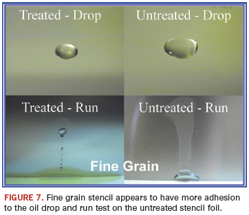
Nickel. Nickel has been supplied in various forms, from electroless nickel plating to the actual electroforming process. Nickel has an excellent natural lubricity and has had various technical publications promoting its superior paste release characteristics. The drop and bead test using the oil revealed characteristics far from the level of repellency required for good paste release, however (Figure 8).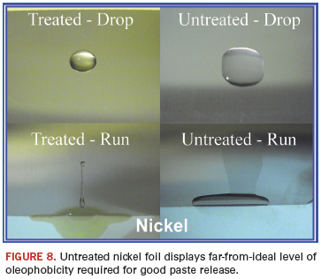
Nano-coated stencils may offer a wider process window and aid process maintenance. All of this can lead to higher throughput, higher first pass yield and aid with sensitive processes.4 It would be wise to review the longevity of such coatings, as there will be a cost involved, and if the coating life is only measured in a few thousand cycles, then the total value will need to be reviewed.
To summarize the key points regarding nano-coated stencils:
- Phobicity: Does the technology exhibit the flux/oil repellency required for successful process control?
- Durability: Long “economical” usable life that fits the assembly environment.
- Lead time: Does the technology fit within the quick turnaround demand?
- Cost: Compare price to performance and process needs.
- Coating technology: How is it applied and can it be re-applied if minor damage has occurred?
- From an in-depth exposure to this technology, it became clear that various coating methodologies are utilized. However, the underlying technology shows promise to bring the stencil capability to the next level of process performance.
References
1. Alan Rae, “Nanotechnology Is Now Starting to Find Applications in Electronics,” SMTA Pan Pacific Symposium, January 2010.
2. Carmina Läntzsc, “Nano-Coated SMT Stencil with Anti-Adhesion Effect: A Novelty in Electronic Production,” EPP, September 2008.
3. Stephanie Brochet, “Mechanical Behaviour of Ultra-Fine Grained Austenitic Stainless Steel, Fracture of,” Nano and Engineering Materials and Structures, 2006.
4. Miguel A. Lara, “Laser-cut Electropolish and Laser-cut Nanocoat Stencils: A Comparison of Finish Performance for Complex Designs,” SMT, April 2010.
Ricky Bennett is president and CEO of Assembly Process Technologies (assemblyprocesstechnologies.com); rickybennett@assemblyprocesstechnologies.com.
Press Releases
- Cofactr Democratizes their Complete Procure-to-Ship Automation Service at a Pivotal Moment for US, Unlocking Support for Agile Hardware Manufacturers in America—with No Upfront Costs
- Semi-Kinetics Adds 2nd Pemtron X-Ray Inspection and Component Counting Capabilities as Part of California Expansion
- The Training Connection Continues to Grow with Addition of Veteran IPC Trainer Bill Graver
- Where Innovation Meets Insight: Luminovo Hosts Premier Munich Electronics Night 2025 Ahead of productronica


